Method for spray forming a metal component and a spray formed metal component

a metal component and metal technology, applied in the direction of manufacturing tools, magnetic bodies,foundry moulding apparatus, etc., to achieve the effects of enhancing cooling, improving component life, and high material quality

Inactive Publication Date: 2009-09-03
VALTION TEKNILLINEN TUTKIMUSKESKUS
View PDF8 Cites 2 Cited by
  • Summary
  • Abstract
  • Description
  • Claims
  • Application Information

AI Technical Summary

Benefits of technology

[0012]Preferably the strip has a cross-sectional profile of an open arc, for example a half circle. This kind of profile enables easy manufacturing of the component as described above.
[0013]The metal component of the present invention can be for example a die insert, a tool, or some other component necessitating high material quality achievable by a spray forming process. Examples are tools used at elevated temperatures, for instance, in die-casting, injection moulding, blow moulding, and hot working. Enhanced cooling will not only improve the component lifetimes, but also increase the productivity by reducing the part cycle time. In plastic injection moulding, for example, conformal cooling has been shown to reduce part cycle time by 15-50% compared to standard cooling practices.

Problems solved by technology

Spray blocking means that the metal spray can not penetrate through the spray blocking object.

Method used


Image

  • Method for spray forming a metal component and a spray formed metal component
  • Method for spray forming a metal component and a spray formed metal component
  • Method for spray forming a metal component and a spray formed metal component

Examples


Embodiment Construction

[0019]Reference will now be made in detail to the embodiments and examples relating to the present invention, which are illustrated in the accompanying figures.

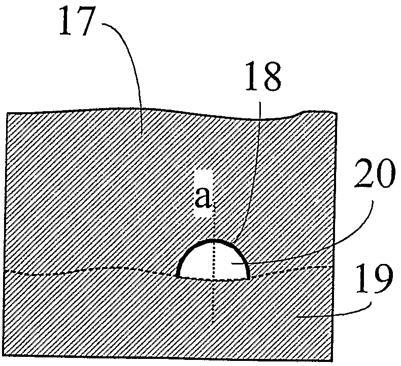
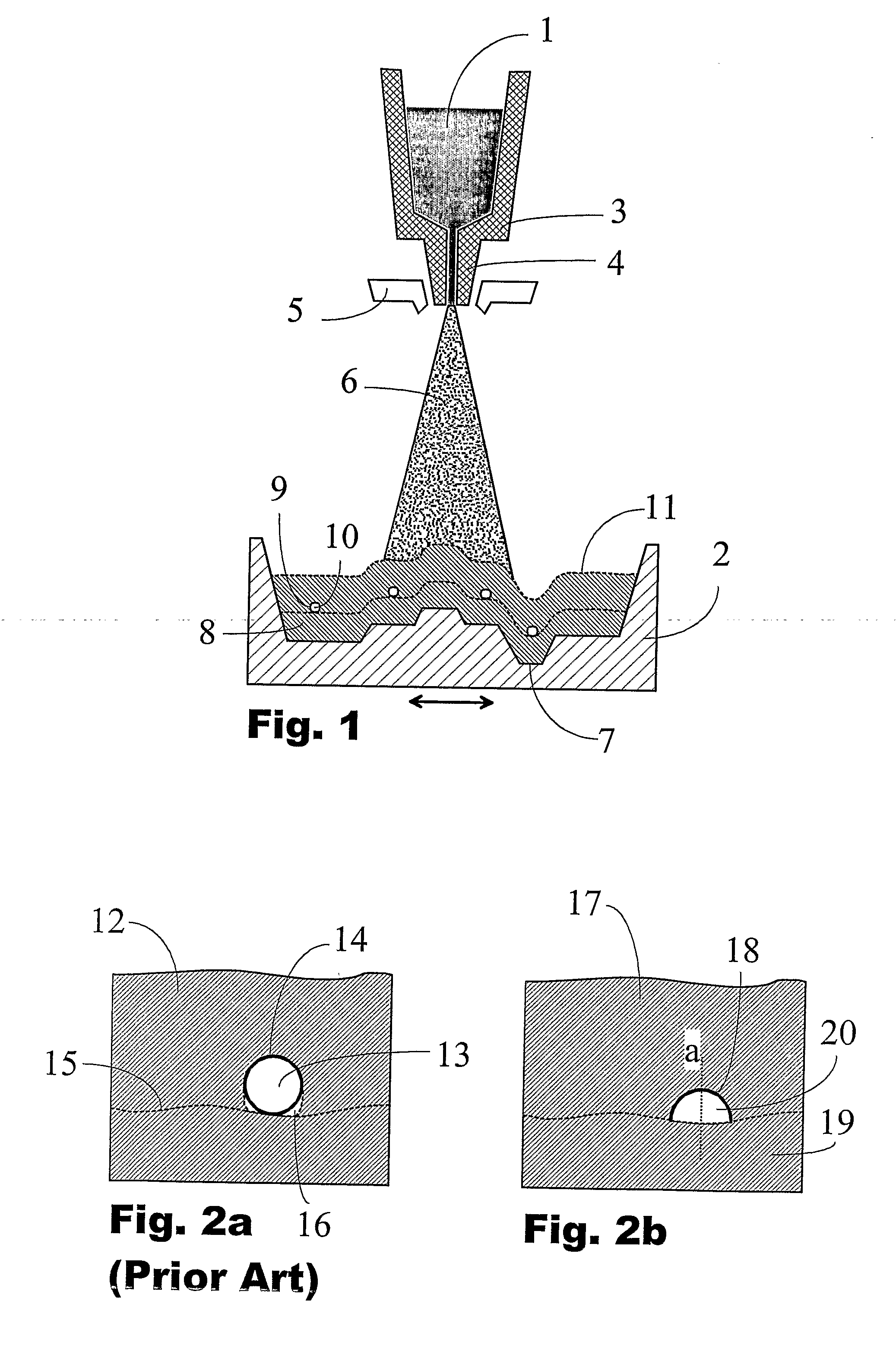
[0020]The arrangement of FIG. 1 illustrates the method of spray forming metal components with cooling channels. Molten metal 1 to be sprayed onto a ceramic mould 2 is fed from a heated reservoir 3 through a nozzle 4 and an atomizer 5 where metal is mixed to cool inert gas, resulting in a spray 6 of rapidly cooling metal droplets directed to the mould. At the mould 2 the metal deposits so as to have a fine and homogenous microstructure producing a nearly net-shape component surface 7. The mould 2 is movable horizontally with respect to the nozzle for covering by the spray 6 the whole mould area. As shown in the figure, after growth of a layer 8 with a substantially uniform thickness, elongated shading objects 9 have been laid on said layer in order to form open channels 10 within the sprayed structure 11 during continuation of...


PUM

PropertyMeasurementUnit
sizeaaaaaaaaaa
thicknessaaaaaaaaaa
thermal propertiesaaaaaaaaaa

Abstract

A method for spray forming a metal component (11, 17, 21, 27) having an elongated open channel (10, 20, 22, 28) therein comprises firstly spray forming a layer (8, 19, 24) of the desired metal onto a deposition substrate (2), placing then an elongated spray blocking object (9, 18, 26, 29) on the already sprayed layer for forming the channel, and continuing then the spray forming process until the desired total thickness of the component is achieved. According to the present invention, the spray blocking object is a strip (18, 26,29), the cross-sectional profile of the strip being fully open in the direction of an axis (a) in a cross-sectional plane of the strip, and the strip is placed on the already deposited layer (8, 19, 24) with said axis directed substantially parallel to the direction of the incident metal spray (6).

Description

FIELD OF THE INVENTION[0001]The present invention relates to manufacturing of metal components with cooling channels by spray forming techniques, and to such components.BACKGROUND OF THE INVENTION[0002]Spray forming is a unique solidification process in which metal melt is atomised by inert gas into droplets of 10-200 microns in size, flying at subsonic speed onto a deposition substrate. During the flight the droplets are rapidly cooled with a cooling rate between 100 to 100,000 degrees per second in a controlled way so that the solidification of the metal is not dependent on the temperature and / or the thermal properties of the deposition surface like a mould. The particles arriving at the mould are in such a condition that welding to the already deposited metal is complete and no interparticle boundaries are developed. As a result, high-quality materials are made with fine, equiaxed and homogeneous microstructures. These features are especially prominent in making high-alloy metal ...

Claims


Application Information

Patent Timeline
Patent Type & Authority Applications(United States)
IPC IPC(8): B32B3/26B22F3/00B22D23/00B22F
CPCB22F3/115C23C4/02C23C4/121Y10T428/12B22F5/007B22F7/06B22F5/10C23C4/123
Inventor YANG, YUNFENG
Owner VALTION TEKNILLINEN TUTKIMUSKESKUS
Why Eureka
Try Eureka