[0008]The present invention proposes a device for removing an element, e.g. a vascular occluding element, from within a lumen of a patient. Such an element can e.g. be a
stent, an occluder, a cage, an
implant or some other device which had previously been positioned, embolized or left e.g. within the vascular lumen for example an
artery or the heart of the patient. It may however also be material which has been deposited within a lumen of the patient by virtue of
natural processes like for example plugs of agglutinated blood, deposits as generated in atherosclerosis, or the like. Generally it may be used in any lumen of a patient, so in a vascular lumen but also in another lumen like the
stomach, a bladder or the like. Such a device comprises a tubular catheter body made of a flexible, typically plastic or
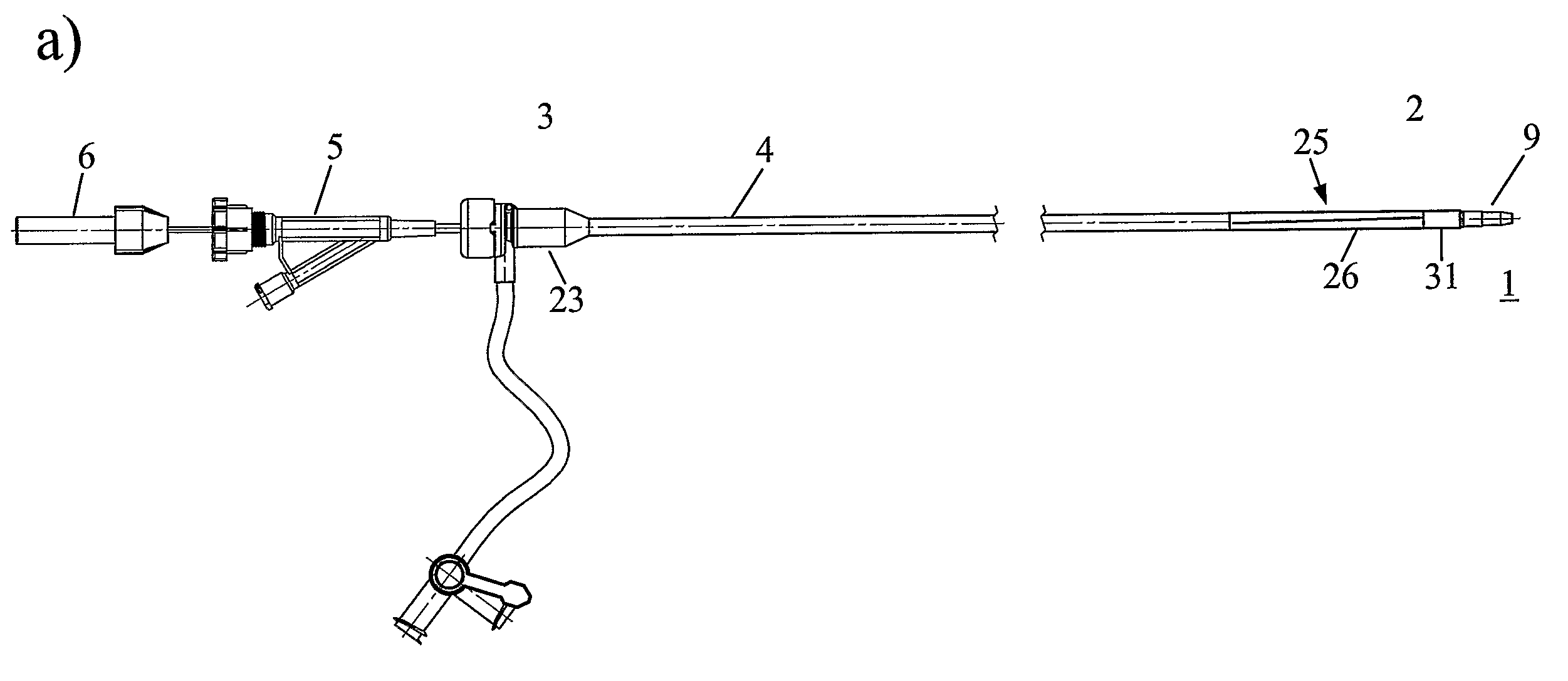
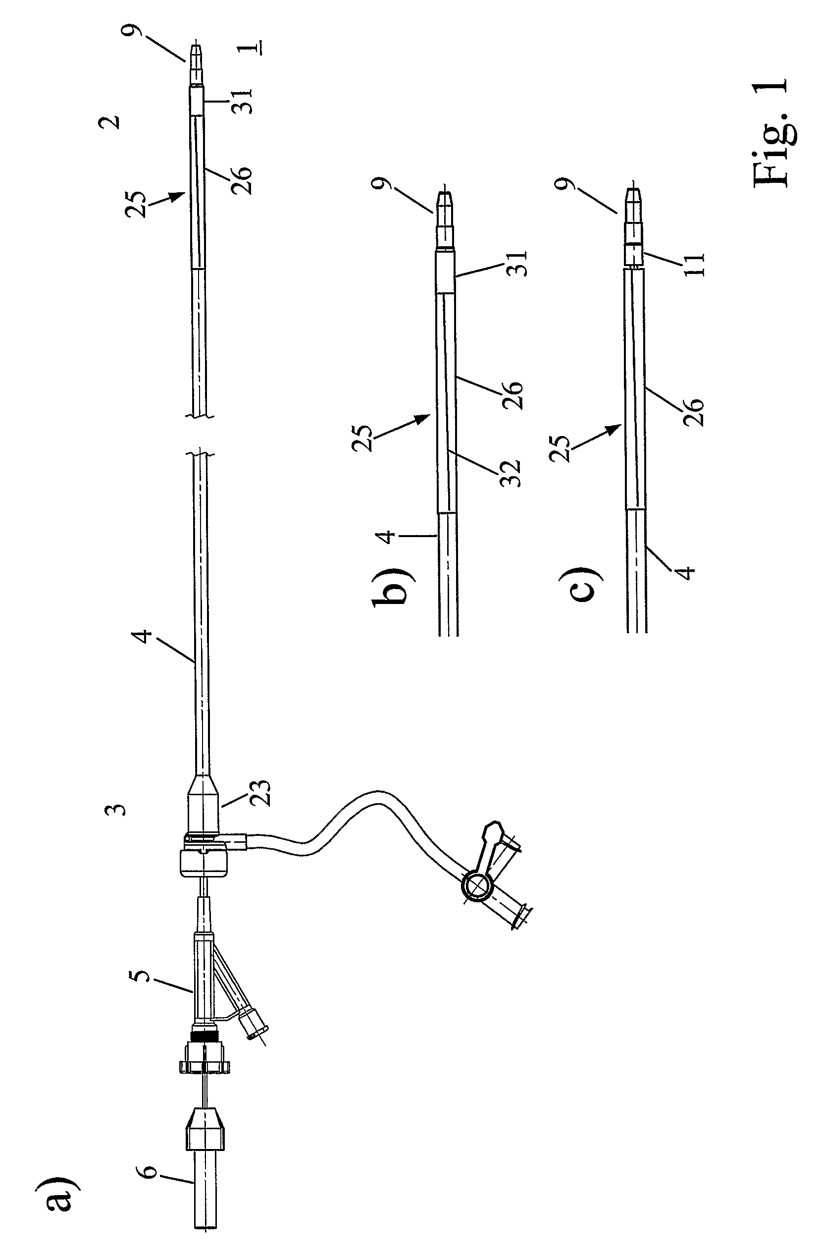
metal material, with a proximal end, which in use is located outside of the body of the patient, and a distal end, which in use is located in the or at the lumen of the patient where the treatment or manipulation shall take place. Typically, on its proximal end such a tubular catheter body comprises fittings for introducing further tools or liquids and the like. The tubular catheter body therefore comprises a central duct or opening or channel through which further devices like for example manipulating catheters can be guided to the lumen of the patient from the outside of the patient. Specifically, the tubular catheter body comprises at its distal end a distal expansion area, which expansion area has a contracted or folded state in which the outside
diameter of the expansion area is substantially equal to or slightly smaller than the outside diameter of the tubular catheter body, thus facilitating and allowing introduction of the device into the patient's body. This expansion area can be brought into a preferably rather stiff expanded state in the or at the lumen of the patient, so after
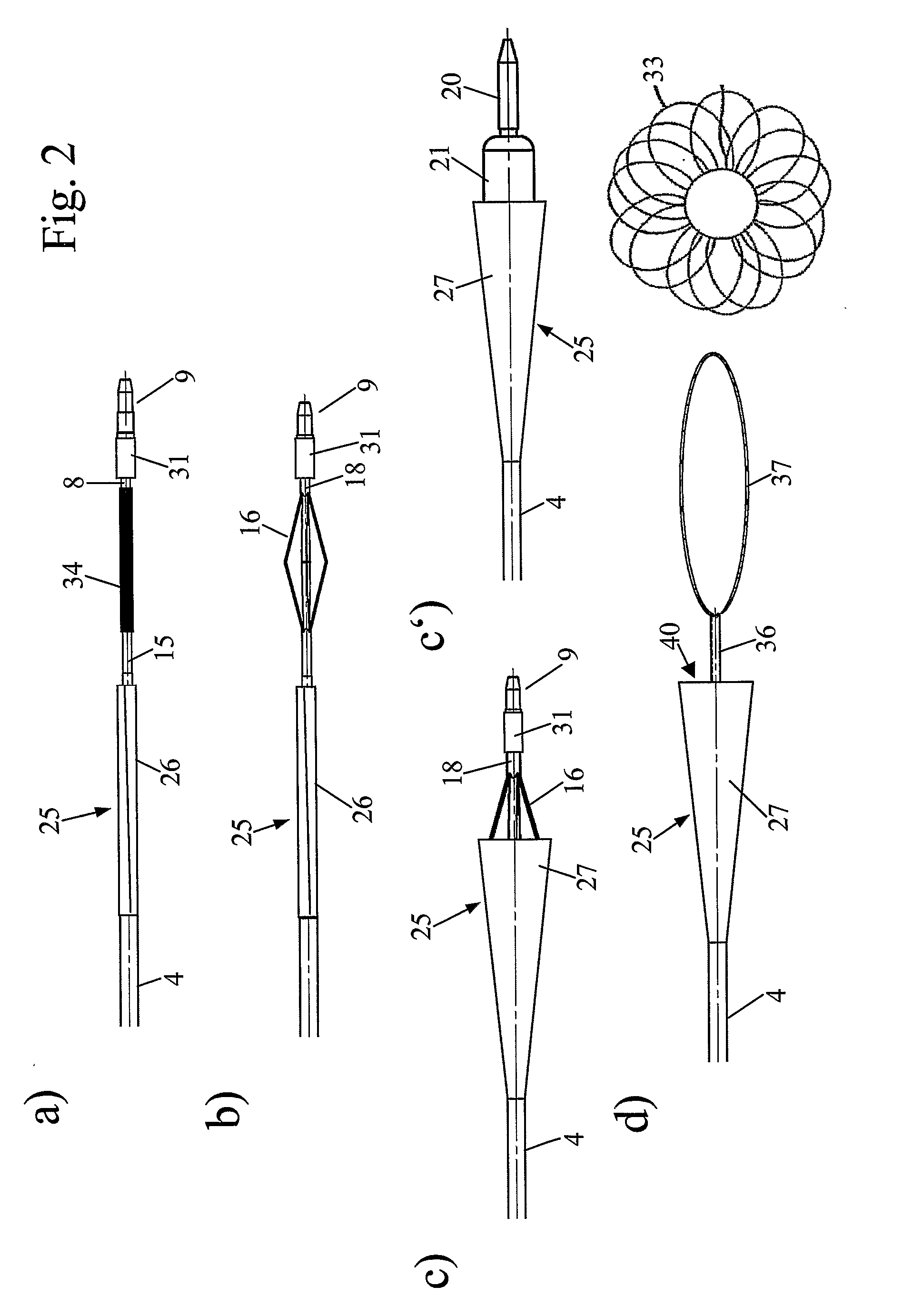
insertion of the catheter to the lumen of the patient. The expanded state comprises an at least partially conical portion opening towards the distal end, such that e.g. an occluding element can be drawn into the expansion area in its expanded state. This specific structure allow us to introduce the folded or contracted catheter through e.g. a body
vein or
artery with a small diameter and using conventional systems at the introduction point of the catheter into the patient's body. The funnel-like structure at the distal end, which can be generated after
insertion of the catheter to its final operating position, allows to withdraw the e.g. occluding elements into this narrowing portion, in case of a
stent or an occluder usually leading to a destruction of this element but at the same time making sure that it is brought into a collapsed state and is well covered by the expansion area. Withdrawing the catheter comprising the element from the patient's body is subsequently possible easily due to the streamlined form of the expansion area.
[0009]Thus this surprisingly simple structure allows a simple and efficient removal of elements, which have to be removed for example because they have embolized, dislocated or because they have been mispositioned, because they are not necessary anymore or because they have deteriorated in some other way.
[0013]According to another preferred embodiment of the present invention, the tubular catheter body and the expansion area are tubes or, as mentioned above, preferably a
single tube forming the tubular catheter body and the expansion area, made of a polymeric material. Possible materials are polyether block amides (e.g. Pebax®),
polyethylene,
polyamide, polytetrafluorethylene,
silicone, polyvinylchloride,
polyurethane, polyethyleneterephthalate,
polypropylene or copolymers, combinations or mixtures thereof. To provide sufficient stiffness and at the same time sufficient flexibility, such a tube typically has a wall thickness of in the range of 0.1-0.5 mm, and for example a
hardness of at least 60
Shore, preferably of at least 70
Shore. Possible is for example a tube made of Pebax® with an outer diameter of 2.5-3 mm such as to fit through standard 3.3 mm in diameter insertion
coupling element (introducer), wherein the tube has a wall thickness of 0.3 mm. Typically therefore, the tubular catheter body has an outer diameter in the range of 1-4 mm, preferably of 2-3 min, and preferentially the expanded state of the expansion area has a distal opening with a diameter in the range of 4-7 mm, preferably of at least 5 mm to efficiently allow withdrawing of occluding elements into the funnel-like structure.
[0018]As mentioned above, expansion of the expansion area may take place automatically after release for example after removal or shifting of the above-mentioned sleeve, it may however also be effected by a specific additional catheter element. So according to another preferred embodiment, further an expander catheter is provided either in addition to or as part of the
dilator, said expander catheter comprising an expander which can be expanded in the lumen of the patient to bring the expansion area from the contracted or folded state into the expanded state. The expander can for example be a contraction expander expanding upon retraction of the
dilator tip. A particularly simple construction is possible if as such a contraction expander a
metal or plastic tube is used, which, in a
distal portion, comprises axial slits, such that the stripes formed by these slits expand in a radial direction if the
dilator tip is retracted with respect to the
metal or plastic tube of the expander. Typically these stripes are already provided with some kind of pre-bending or kinks, such that a proper
radial motion results upon retraction of the dilator tip. In the alternative, the expander can also be a
balloon catheter, preferably a
balloon catheter with the dilator tip provided at its distal end. In this case, expansion can be effected by filling the
balloon catheter with a corresponding fluid, which, if a specific fluid like a marker fluid is used, in addition to that allow us proper positioning of the device using imaging techniques.

