Exposure apparatus, method for cleaning member thereof , maintenance method for exposure apparatus, maintenance device, and method for producing device

a technology for exposure apparatus and cleaning parts, which is applied in the direction of photomechanical apparatus, printing, instruments, etc., can solve the problems of insufficient focus margin, difficult to match the substrate surface with respect to the image plane of the projection optical system, and generation of impurities

Inactive Publication Date: 2009-09-10
NIKON CORP
View PDF26 Cites 35 Cited by
  • Summary
  • Abstract
  • Description
  • Claims
  • Application Information

AI Technical Summary

Benefits of technology

[0008]In order to achieve the objects as described above, the present invention adopts the following constructions corresponding to FIGS. 1 to 17 as illustrated in embodiments. However, parenthesized reference numerals affixed to respective elements merely exemplify the elements by way of example, with which it is not intended to limit the respective elements.
[0009]According to a first aspect of the present invention, there is provided an exposure apparatus (EXS, EX) which exposes a substrate (P) through a liquid (LQ); the exposure apparatus comprising a projection optical system (PL), a liquid immersion area (AR2) of the liquid (LQ) being formed on a side of an image plane of the projection optical system (PL); and an optical cleaning device (optical cleaning unit) (80) which radiates a predetermined radiation light beam (Lu) having an optical cleaning effect onto a member (for example, 2, 31, 70, 300, 400, 500, 600) which makes contact with the liquid (LQ) for forming the liquid immersion area (AR2).
[0010]According to the first aspect of the present invention, the optical cleaning is performed such that the radiation light beam, which has the optical cleaning effect, is radiated by using the optical cleaning device onto the member which makes contact with the liquid forming the liquid immersion area. Accordingly, it is possible to remove any pollutant from the member:
[0011]According to a second aspect of the present invention, there is provided an exposure apparatus (EXS, EX) which exposes a substrate (P) through a liquid (LQ); the exposure apparatus comprising a projection optical system (PL), an optical path space on a side of an image plane of the projection optical system (PL) being filled with the liquid (LQ); a nozzle member (70) which fills the optical path space with the liquid (LQ); and a vibration mechanism which vibrates at least a part of the nozzle member (70) to remove a pollution matter adhered to the nozzle member (70).
[0012]According to the second aspect of the present invention, the pollution matter, which is adhered to the nozzle member, can be removed by vibrating the nozzle member with the vibration mechanism.
[0013]According to a third aspect of the present invention, there is provided a method for producing a device, comprising using the exposure apparatus (EXS, EX) as defined in any one of the aspects described above.

Problems solved by technology

If the depth of focus δ is too narrowed, it is difficult to match the substrate surface with respect to the image plane of the projection optical system.
It is feared that the focus margin is insufficient during the exposure operation.
That is, any impurity generated, for example, from the surface of the substrate, may enter into and contaminate the liquid of the liquid immersion area.
If the liquid immersion area of the liquid, which contains the impurity, is moved on the substrate stage, there is such a possibility that the upper surface of the substrate stage (including the upper surface of the measuring section provided on the substrate stage) may be polluted with the impurity.

Method used


Image

  • Exposure apparatus, method for cleaning member thereof , maintenance method for exposure apparatus, maintenance device, and method for producing device
  • Exposure apparatus, method for cleaning member thereof , maintenance method for exposure apparatus, maintenance device, and method for producing device
  • Exposure apparatus, method for cleaning member thereof , maintenance method for exposure apparatus, maintenance device, and method for producing device

Examples


first embodiment

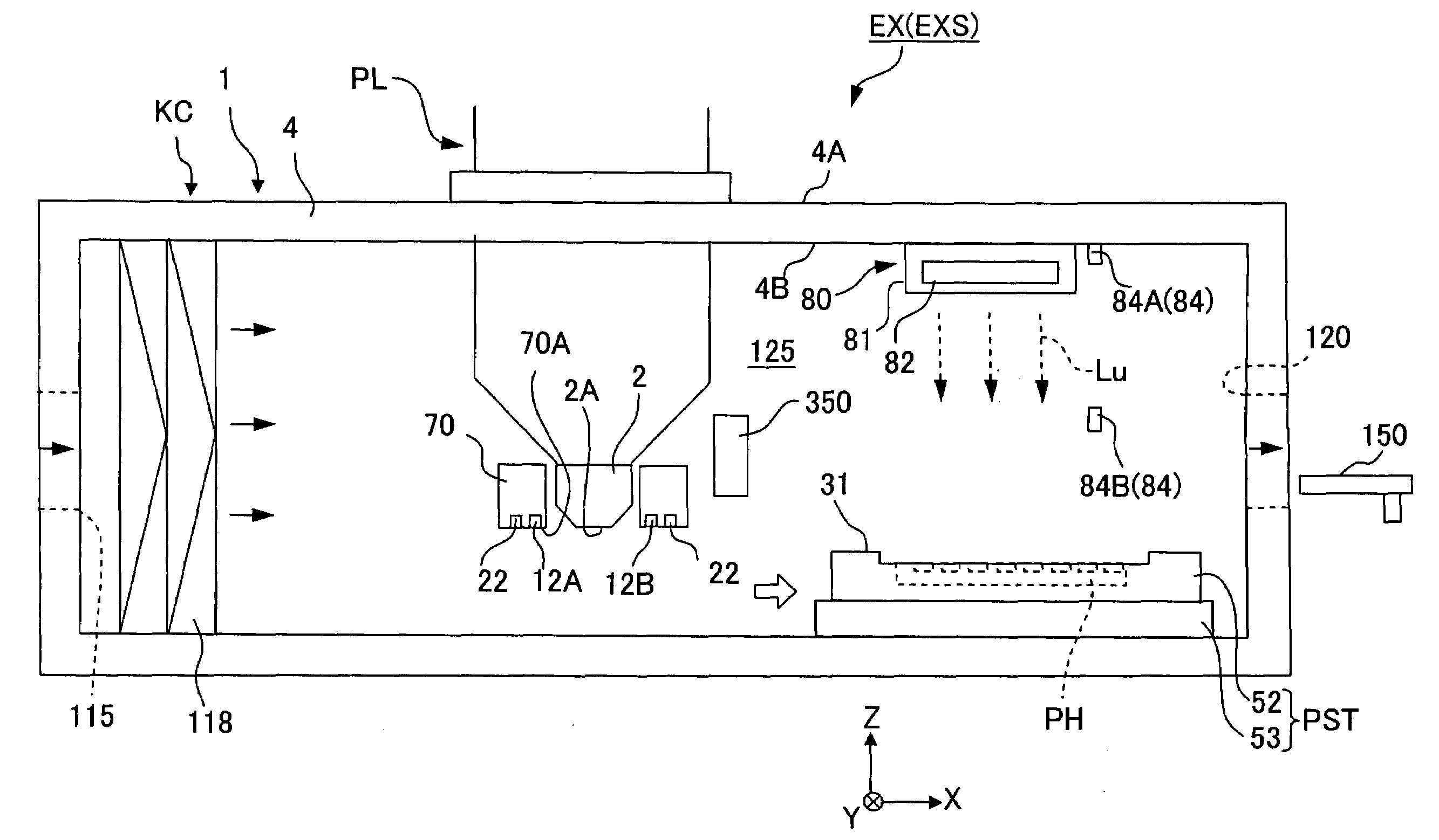
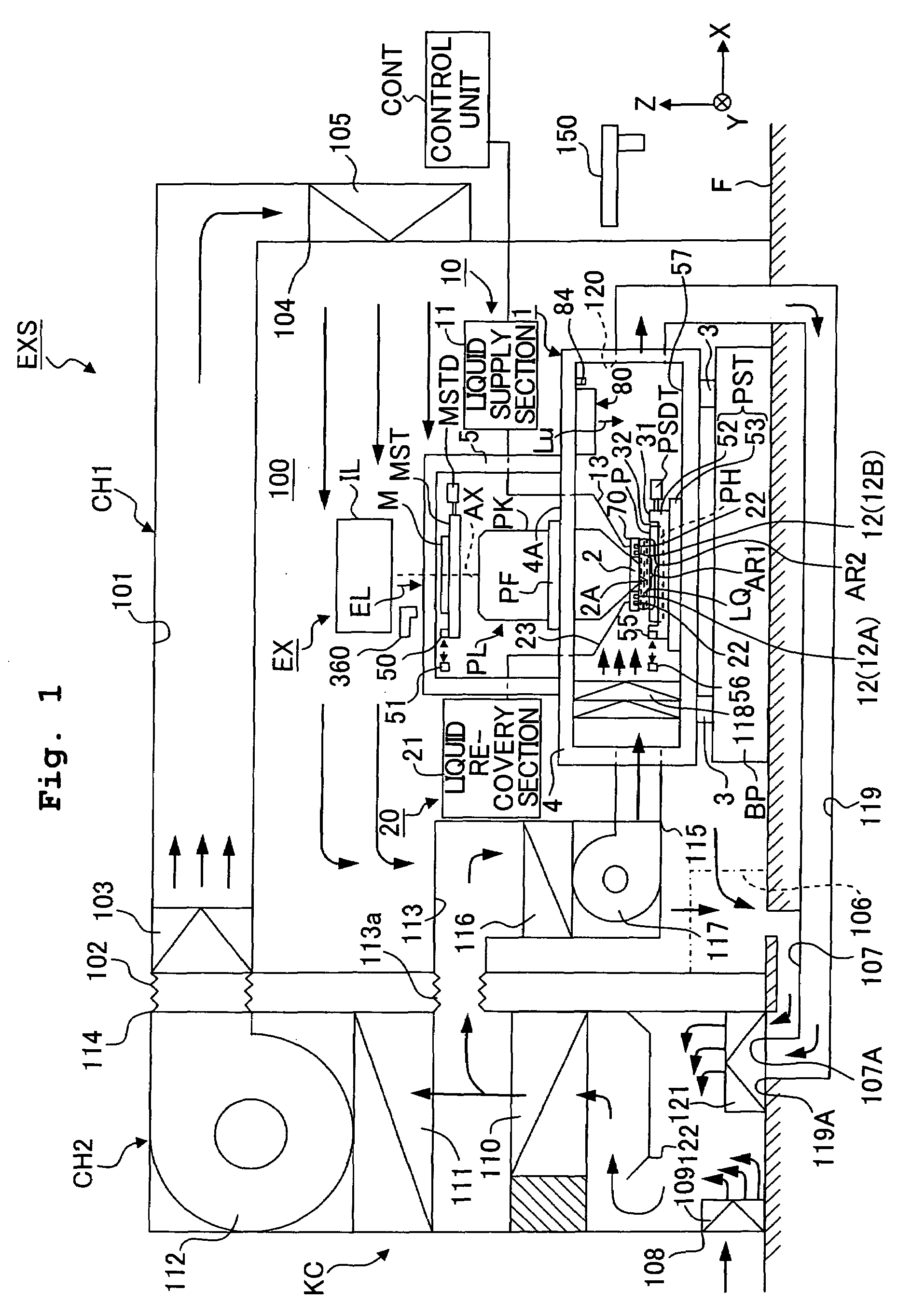
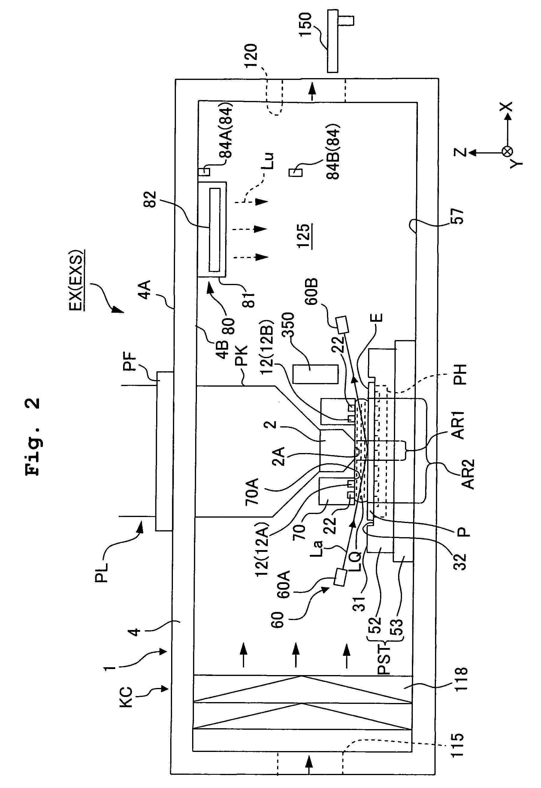
[0041]FIG. 1 shows a schematic arrangement illustrating a first embodiment of an exposure apparatus of the present invention, and FIG. 2 shows a magnified view illustrating main components shown in FIG. 1. With reference to FIG. 1, the exposure apparatus EXS includes a body chamber (chamber for exposure apparatus body) CH1 which is installed on a floor surface F in a clean room, and a machine chamber CH2 which is arranged adjacently to the body chamber CH1. An exposure chamber 100, which is provided in the body chamber CH1, is air-conditioned by an air-conditioning system KC. The internal environment (for example, cleanness, temperature, pressure) is maintained to be substantially constant. In this embodiment, the exposure chamber 100 is filled with the clean air. An exposure apparatus body (body of exposure apparatus) EX is accommodated in the exposure chamber 100. The exposure chamber 100 is connected to an outlet 114 of a gas flow passage provided in the machine chamber CH2, via ...

second embodiment

[0118]FIG. 5 shows a schematic arrangement illustrating a second embodiment of the present invention. In the following explanation, constitutive parts or portions, which are the same as or equivalent to those of the embodiment described above, are designated by the same reference numerals, any explanation of which will be simplified or omitted.

[0119]As described above, the optical cleaning unit 80 (light source 82) serves as the heat-generating source. Therefore, the optical cleaning unit 80 (light source 82) may be arranged outside the air-conditioned space 125 as shown in FIG. 5. Accordingly, it is possible to more effectively avoid the conduction of the heat generated by the optical cleaning unit 80 to the projection optical system PL (optical path for the exposure light beam EL). With reference to FIG. 5, the optical cleaning unit 80 is provided on the upper surface 4A of the main column 4, and is arranged outside the air-conditioned space 125. A transmissive window 83, through ...

third embodiment

[0121]FIG. 6 shows a third embodiment. With reference to FIG. 6, an optical cleaning unit 80 includes a light source 82 which is arranged outside the air-conditioned space 125 and which radiates the ultraviolet light beam Lu, and an optical system 86 which guides the ultraviolet light beam Lu radiated from the light source 82 onto the substrate stage PST arranged inside the air-conditioned space 125. The optical system 86 includes a transmissive window 83 which is provided at a part of the side wall of the main column 4 on the +X side and through which the ultraviolet light beam Lu is transmissive, and a reflecting mirror 85 which is arranged inside the air-conditioned space 125 and which bends the optical path for the ultraviolet light beam Lu allowed to pass through the transmissive window 83. The transmissive window 83 is formed of a material which scarcely absorbs the ultraviolet light beam Lu, including, for example, silica glass, calcium fluorite, and magnesium fluoride, in th...


PUM

PropertyMeasurementUnit
areaaaaaaaaaaa
adhesionaaaaaaaaaa
liquid-attractive propertyaaaaaaaaaa

Abstract

An exposure apparatus forms an immersion area of a liquid on the side of the image plane of a projection optical system and performs exposure of a substrate via the projection optical system and the liquid of the immersion region. The exposure apparatus has an optical cleaning unit which irradiates a predetermined irradiation light, having an optical cleaning effect, onto, for example, the upper surface of the substrate stage which makes contact with the liquid for forming the immersion area. Thus, it is possible to prevent deterioration of the exposure accuracy and measurement accuracy due to pollution of the member in contact with the liquid in the immersion region.

Description

TECHNICAL FIELD[0001]The present invention relates to an exposure apparatus which exposes a substrate through a liquid, a method for cleaning a predetermined member which constructs the exposure apparatus, a maintenance method for the exposure apparatus, a maintenance device, and a method for producing a device.BACKGROUND ART[0002]Semiconductor devices and liquid crystal display devices are produced by the so-called photolithography technique in which a pattern formed on a mask is transferred onto a photosensitive substrate. The exposure apparatus, which is used in the photolithography step, includes a mask stage for supporting the mask and a substrate stage for supporting the substrate. The pattern on the mask is transferred onto the substrate via a projection optical system while successively moving the mask stage and the substrate stage. In recent years, it is demanded to realize the higher resolution of the projection optical system in order to respond to the further advance of ...

Claims


Application Information

Patent Timeline
Patent Type & Authority Applications(United States)
IPC IPC(8): G03B27/52G03F7/20H01L21/027
CPCG03F7/70341G03F7/7085G03F7/2041G03F7/70925G03F7/70916H01L21/0274G03F7/708
Inventor NAGASAKA, HIROYUKISHIRAISHI, KENICHIOWA, SOICHIHIRUKAWA, SHIGERU
Owner NIKON CORP
Why Eureka
Try Eureka