
Patterned assembly for manufacturing a solar cell and a method thereof

a solar cell and assembly technology, applied in the field of solar cell system manufacturing, can solve the problems of affecting the doping process, and releasing contaminants from the excess hea

Inactive Publication Date: 2009-09-10
VARIAN SEMICON EQUIP ASSOC INC
View PDF15 Cites 51 Cited by
  • Summary
  • Abstract
  • Description
  • Claims
  • Application Information

AI Technical Summary

Benefits of technology

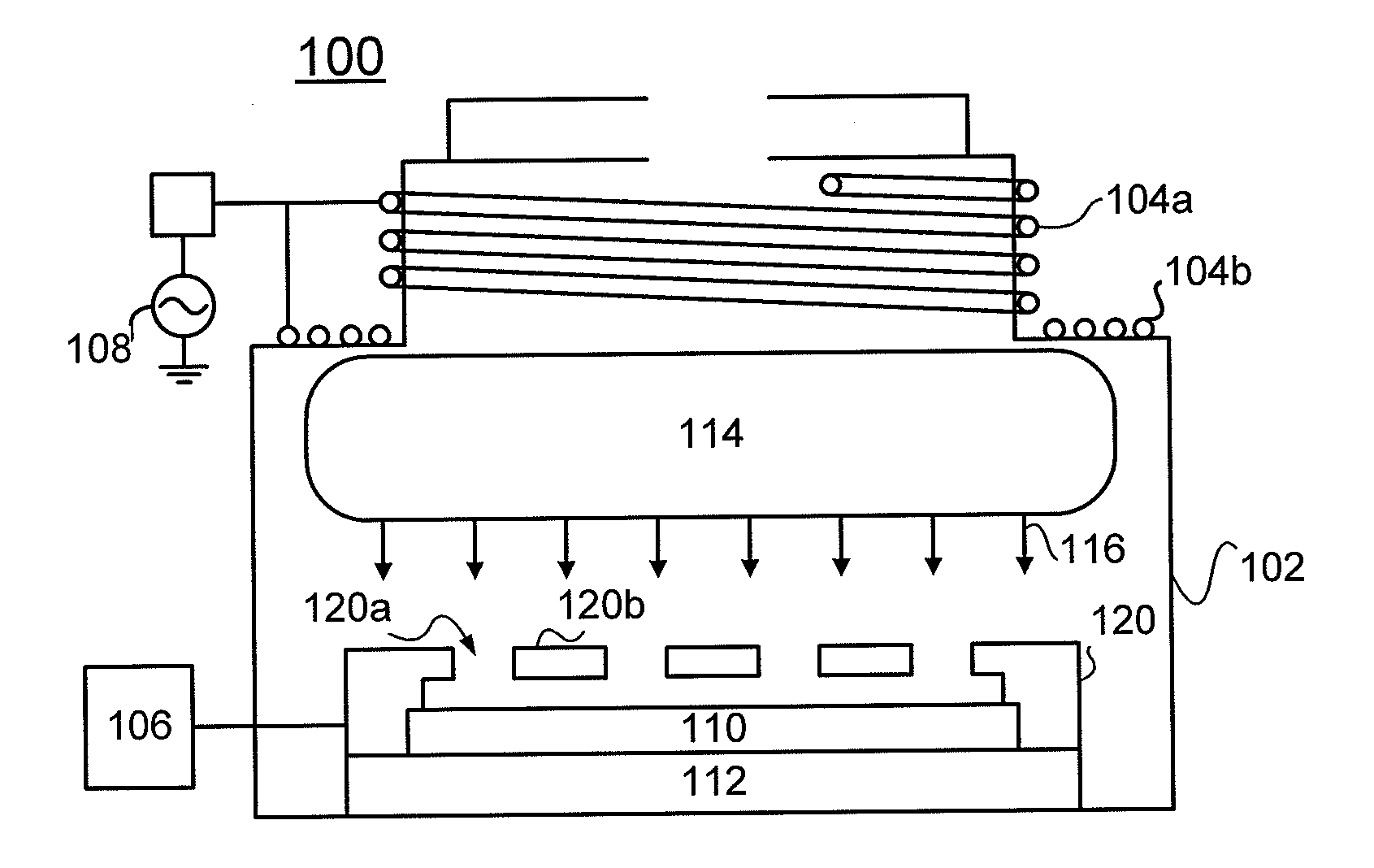
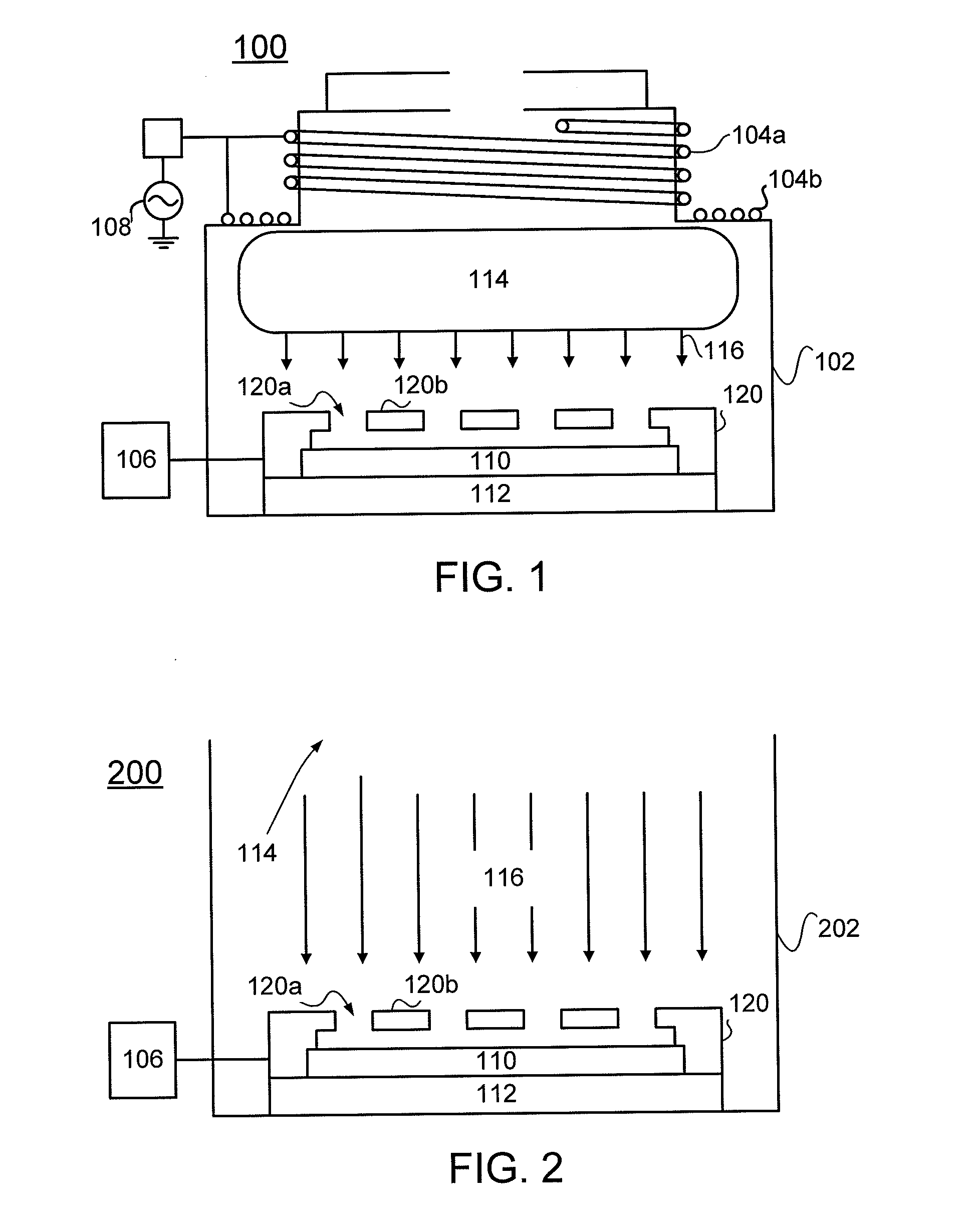
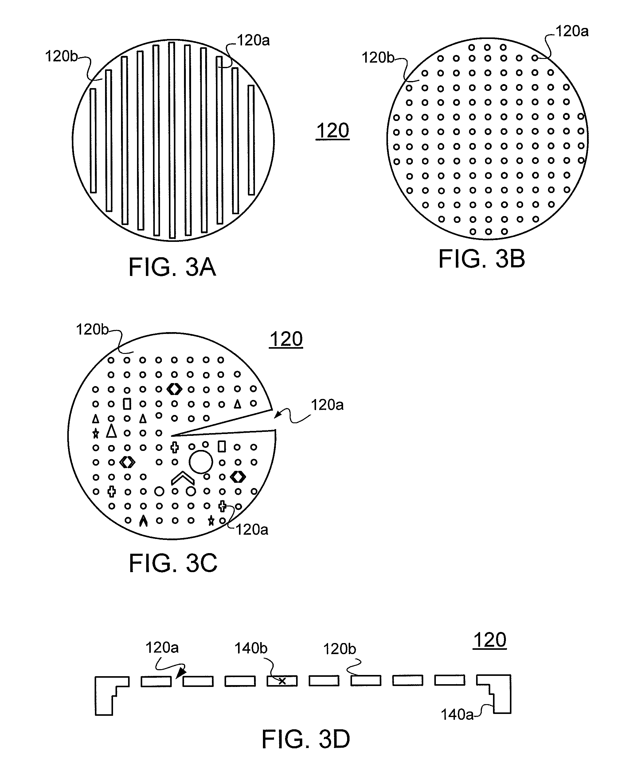
[0011]An apparatus and a method for manufacturing a solar cell are disclosed. In a particular embodiment, the solar cell may be manufactured by disposing a solar cell in a chamber having a particle source; disposing a patterned assembly comprising an aperture and an assembly segment between the particle source and the solar cell; and selectively implanting first type dopants traveling through the aperture into a first region of the solar cell while minimizing introduction of the first type dopants into a region outside of the first region.

Problems solved by technology

If contaminants such as voids or air bubble are present at the glass / solar cell interface, the contaminants may hinder the doping process and / or the doping process may not form uniform doped regions.
As such, excessive heat may release contaminants and introduce the contaminants to the solar cell.
Moreover, excessive heat may degrade the structural integrity of the passivating layer.
The contaminants and the degradation structural integrity may lead to unstable and / or non-repeatable doping condition and / or formation of non-uniform doped regions.
However, cost of the materials having higher melting temperature is very high, and use of such materials for manufacturing solar cells may be impractical.
Application of less heat, however, may not provide uniform doped regions.
Another disadvantage of the conventional solar cell manufacturing process is its use of the diffusion process to form the doped regions.
As known in the art, success of forming uniform doped regions may depend on parameters such as dopant concentration gradient in both of the doped glasses and the solar cell and application of uniform temperature, parameters that are difficult to control.
As such, forming uniform doped regions via the conventional diffusion process may be difficult.
Yet another disadvantage of the conventional doping process may be found in the efficiency of the process.

Method used


Image

  • Patterned assembly for manufacturing a solar cell and a method thereof
  • Patterned assembly for manufacturing a solar cell and a method thereof
  • Patterned assembly for manufacturing a solar cell and a method thereof

Examples


Embodiment Construction

[0028]Herein, several embodiments of patterned assembly for manufacturing a solar cell and a method thereof will be disclosed with reference to accompanying drawings. The detailed disclosure contained herein is intended for illustration, for better understanding the disclosure, and not a limitation thereto. Present disclosure may be made with reference to a particular solar cell manufacturing system. For example, the disclosure may be made with reference to a plasma doping (“PLAD”) or a plasma immersion ion implantation (“PIII”) system, or a beam-line ion implantation system. However, the present disclosure is equally applicable to other solar cell manufacturing systems including other types of plasma based or non-plasma based doping systems, plasma based or non-plasma based etching systems, plasma based or non-plasma based deposition systems, and the sprayed wet chemistry systems.

[0029]In addition, specific reference to a particular system does not mean that the system is limited t...


PUM


Abstract

Apparatuses and methods for manufacturing a solar cell are disclosed. In a particular embodiment, the solar cell may be manufactured by disposing a solar cell in a chamber having a particle source; disposing a patterned assembly comprising an aperture and an assembly segment between the particle source and the solar cell; and selectively implanting first type dopants traveling through the aperture into a first region of the solar cell while minimizing introduction of the first type dopants into a region outside of the first region.

Description

PRIORITY[0001]This application claims priority to U.S. provisional patent application Ser. No. 60 / 970,664 filed Sep. 7, 2007 entitled “A Patterned Charged Assembly and A System and A Method Using the Same,” which is incorporated in its entirety by reference.FIELD[0002]This disclosure relates to a system for manufacturing a solar cell, more particularly, to a patterned assembly for manufacturing a solar cell and a method thereof.BACKGROUND[0003]With increase in interest in solar cells, much attention has been placed on improving the process of manufacturing the solar cells. One of sub-processes in manufacturing the solar cell may be a doping process to alter electrical and / or optical property of the solar cell. In a conventional doping process that requires patterned doping a resist or silicon dioxide (“passivating”) layer, portions of the passivating layer may be removed, and portions of the solar cell may be exposed. On the exposed portions, a glass containing n-type dopants (e.g. ...

Claims


Application Information

Patent Timeline
IPC IPC(8): H01L31/18G21G4/00
CPCH01L31/022425Y02E10/547H01L31/068H01L31/03529H01L31/0682H01L31/04H01L31/18
Inventor SULLIVAN, PAULNUNAN, PETERWALTHER, STEVEN R.
Owner VARIAN SEMICON EQUIP ASSOC INC
Learn More