
Gate driver-on-array and method of making the same

a technology of gate driver and gate array, which is applied in the field of gate driver on array, can solve the problems of parasitic capacitance generation in the connection structure, metal precipitation, and tendency to corrosion, and achieve the effects of reducing the layout area, improving electrical reliability, and simplifying the process of goa

Active Publication Date: 2009-09-17
AU OPTRONICS CORP
View PDF5 Cites 24 Cited by
  • Summary
  • Abstract
  • Description
  • Claims
  • Application Information

AI Technical Summary

Benefits of technology

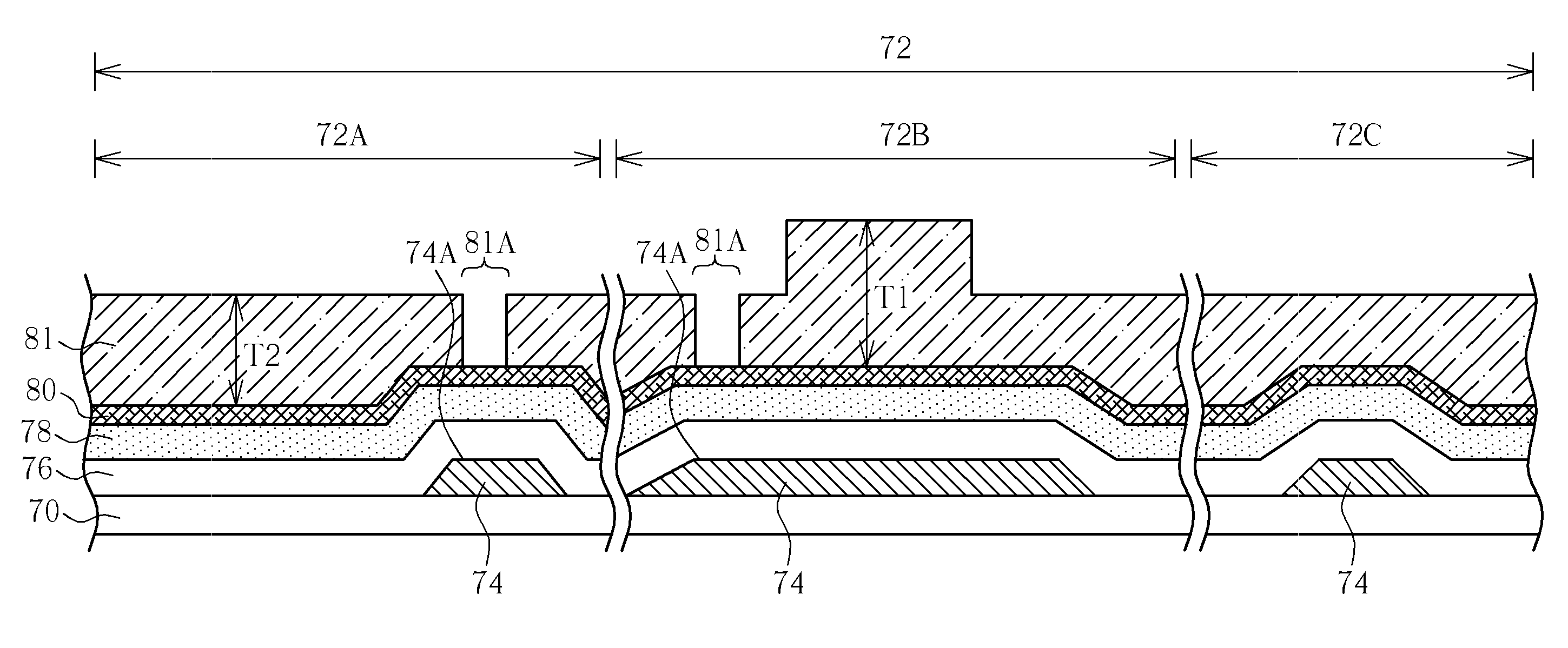
[0008]It is therefore one of the objectives of the present invention to provide a GOA integrated into a display panel (such as TFT-LCD, OLED, LTPS TFT-LCD, and PDP) and method of making the same to reduce the layout area, improve the electrical reliability, and simplify the process of GOA.
[0011]The GOA structure of the present invention uses the second patterned metal layer to overlap and contact the first patterned metal layer without requiring forming through holes in the passivation layer and using the transparent conductive layer to implement electrical connection. Thus, the layout area is reduced, the electrical reliability is improved, and the process of GOA is simplified. In addition, the present invention is not limited to use for liquid crystal displays, and may be broadly applied in various types of display devices.

Problems solved by technology

First, through hole corrosion tends to occur in the through hole areas during subsequent processes, and parasitic capacitances may generate in the connection structure.
Besides, the connection structure made of the transparent conductive layer is disposed under the sealant, which is liable to cause metal precipitate.
This would lead to a poor electrical contact between the first patterned metal layer and the second patterned metal layer, thereby generating wave pulses having abnormal waveform.

Method used


Image

  • Gate driver-on-array and method of making the same
  • Gate driver-on-array and method of making the same
  • Gate driver-on-array and method of making the same

Examples


Embodiment Construction

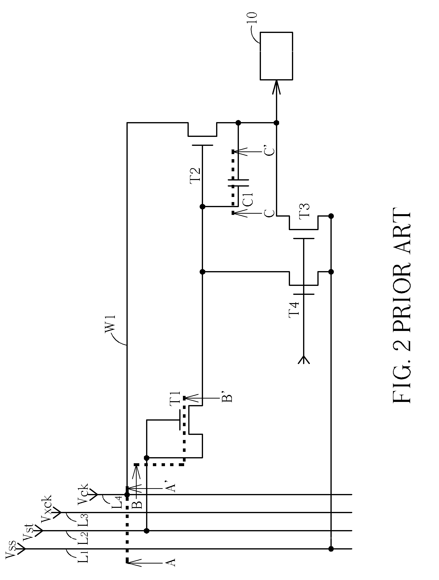
[0019]Referring to FIG. 4 in conjunction with the circuit diagram of the GOA shown in FIG. 2. FIG. 4 is a cross-sectional view of a GOA integrated into a display according to a preferred embodiment of the present invention, which is taken along lines A-A′, B-B′, and C-C′ of FIG. 2, respectively. As shown in FIG. 4, the GOA 50 includes a substrate 52, and a GOA structure 56. The substrate 52, which includes a peripheral region 54 and a pixel region (not shown), is the array substrate (also referred to as TFT substrate) of a liquid crystal display panel, and the GOA structure 56 is disposed in the peripheral region 54 of the substrate 52. The peripheral region 54 includes a signal line connection region 54A, a TFT region 54B, and a capacitor region 54C. The GOA structure 56 from bottom to top includes a first patterned metal layer 58, an insulating layer 60, a semiconductor layer 62, a heavily doped semiconductor layer 64, a second patterned metal layer 66, and a passivation layer 68,...


PUM


Abstract

A gate driver-on-array structure integrated into a display includes a substrate and a gate driver structure formed thereon. The gate driver structure is disposed in a peripheral region of the substrate. The gate driver structure includes a first layer metal pattern, a second layer metal pattern, and an insulating layer disposed therebetween. The first layer metal pattern includes connection nodes. The insulating layer has through holes exposing the connection nodes. The second layer metal pattern fills into the through holes and in contact with the connection nodes of the first layer metal pattern so as to implement necessary electrical connection of the gate driver structure.

Description

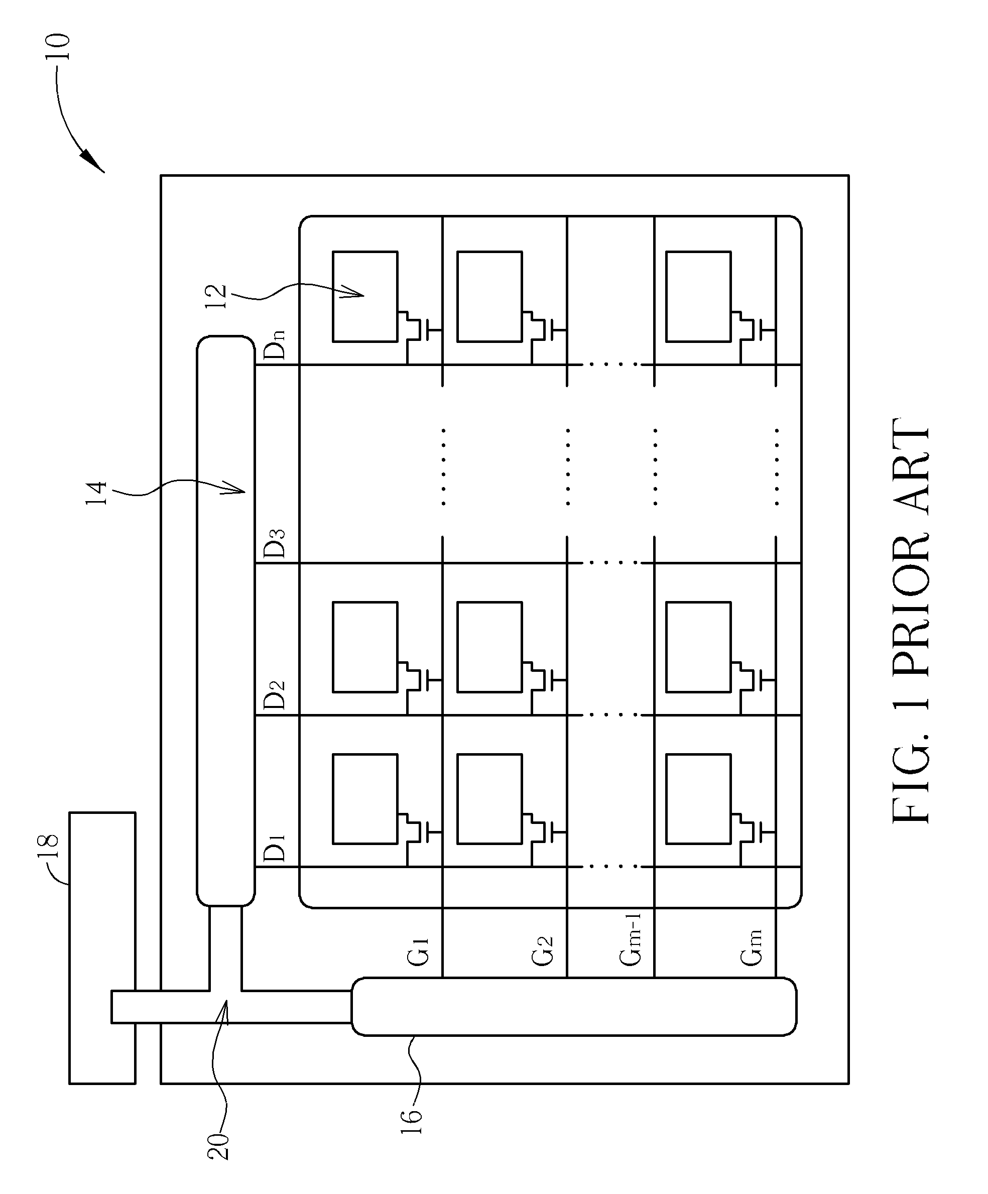
BACKGROUND OF THE INVENTION[0001]1. Field of the Invention[0002]The present invention relates to a gate driver-on-array (GOA) integrated into a display panel and method of making the same, and more particularly, to a GOA in which the electrical connection between a first patterned metal layer and a second patterned metal layer is not implemented by a transparent conductive layer, and method of making the same.[0003]2. Description of the Prior Art[0004]Display panels have been broadly applied in electronic displaying devices, e.g. thin film transistor liquid crystal displays (TFT-LCDs), organic light emitting displays (OLEDs), low temperature polycrystalline silicon (LTPS) TFT-LCDs, plasma display panel (PDP) displays, etc. Refer to FIG. 1. FIG. 1 plan view schematically illustrating a conventional TFT-LCD panel. As shown in FIG. 1, the TFT-LCD panel 10 includes pixels 12 arranged as a matrix. The pixels 12 are controlled by a plurality of data line D1, D2, . . . , Dn, and gate lines...

Claims


Application Information

Patent Timeline
Patent Type & Authority Applications(United States)
IPC IPC(8): G09G3/00H01L21/336
CPCG02F1/13454H01L27/124H01L27/1288
Inventor TSAI, TUNG-CHANGSHIH, MING-CHANG
Owner AU OPTRONICS CORP
Learn More