
Electrochromic compound and electrochromic display device using the same

a display device and electrochromic compound technology, applied in the field of display devices, can solve the problems of low light utilization efficiency, low contrast ratio, and difficult development of display devices offering all of these characteristics

Active Publication Date: 2009-09-17
RICOH KK
View PDF2 Cites 18 Cited by
  • Summary
  • Abstract
  • Description
  • Claims
  • Application Information

AI Technical Summary

Benefits of technology

[0009]The problem to be solved by the present invention is to provide an electrochromic device which can retain coloration and / or decoloration for a longer period of time.
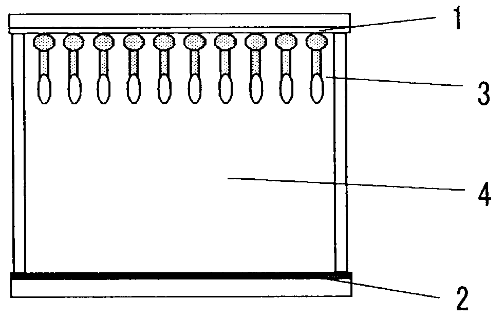
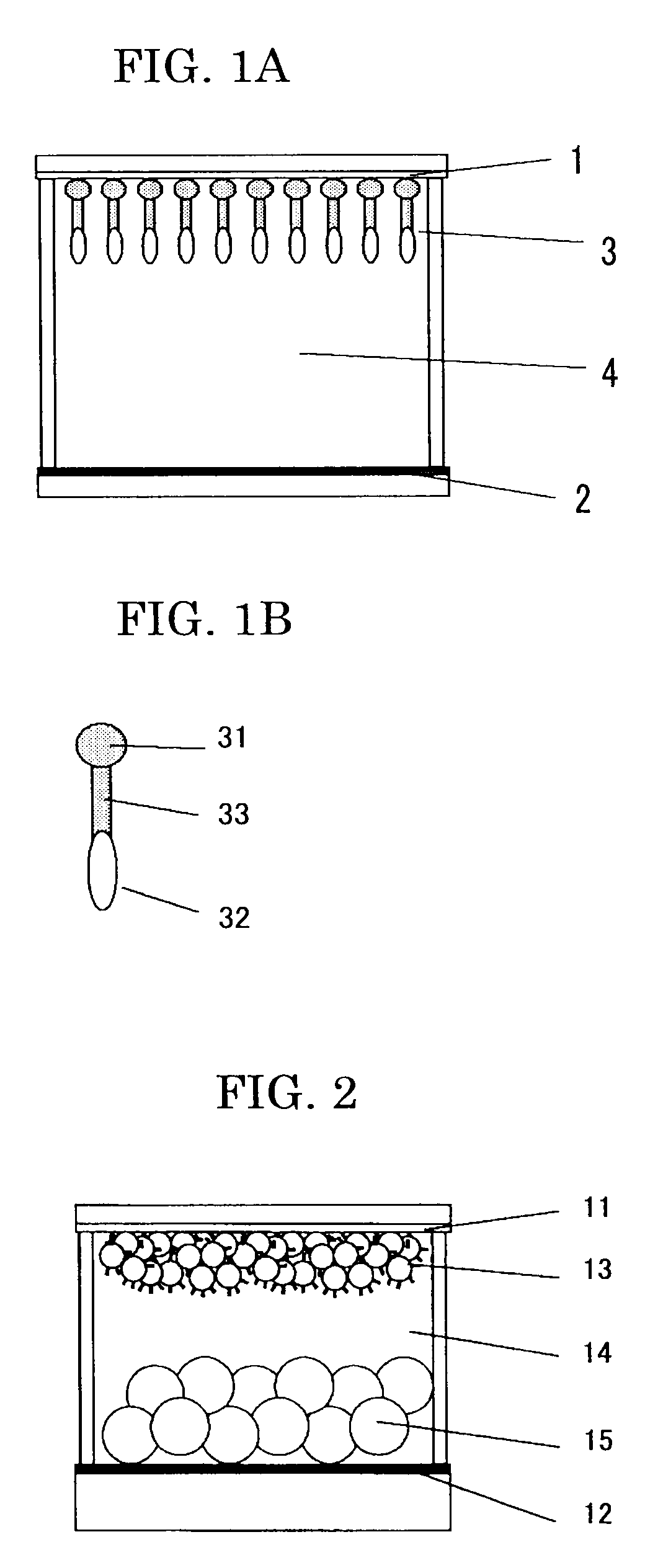
[0026]As the specific and detailed description below will clarify, the present invention achieves extremely excellent effect in providing an electrochromic display device capable of retaining coloring and / or decoloring for a longer period of time by interposing a halogenized carbohydrate group —(CX2)— between the monovalent binding group A, which binds to the electrode to become a site through which electrons are poured into or from the electrode, and the redox chromophore B, which causes, by giving or receiving electrons, a redox reaction producing coloration or decoloration, thereby blocking the stream of electrons from the redox chromophore B to the electrode, suppressing the discharge rate of electrons.

Problems solved by technology

In terms of its display characteristics, in particular, it is required that electronic paper has as excellent white reflectivity and contrast ratio as paper does, and the development of a display device offering all of these characteristics is far from easy.
The media, however, have the following problems: low light-utilizing efficiency due to the use of a polarizing plate; being incapable of displaying colors other than dark white; and low contrast ratio because of incapability of displaying black color.
In such a device, however, it is practically difficult to completely reverse the white particles and the black particles so that it is hard to simultaneously satisfy high white reflectivity and high contrast ratio.
However, it is clear that an excellent image quality cannot be obtained by forming a color filter on a display medium having low white reflectivity and low contrast ratio.
These devices cannot solve the above-mentioned problems in principle, and cannot simultaneously fulfill high white reflectivity and high contrast ratio.
However, the organic electrochromic compounds illustrated in the two publications form colors such as blue and green, but cannot form three primary colors, i.e., yellow, magenta and cyan, which are necessary for producing a full color display.
Although these organic electrochromic compounds can form the three primary colors, they have no memory effect, so that when voltage-applying is stopped, these compounds lose their colors in about one second.
Thus, these compounds cannot be used for electronic paper which needs memory effect.

Method used


Image

  • Electrochromic compound and electrochromic display device using the same
  • Electrochromic compound and electrochromic display device using the same
  • Electrochromic compound and electrochromic display device using the same

Examples


example 1

1) Display Electrode

[0052]0.2 M of Compound No. 11 was dissolved in a mixed solvent of methanol and isopropanol. In the resultant solution, a glass substrate whose whole surface was covered with tin oxide transparent electrode film was immersed for 24 hours to allow Compound No. 11 to adsorb on the surface of the electrode, whereby a display electrode was produced.

2) Counter Electrode

[0053]10 g of titanium oxide (a white pigment) was mixed with 10% methylethylketone solution (10 g) of acryl resin, and the mixture was dispersed for 1 hour with 2 mm zirconia beads (50 g) using a ball mill. The resultant dispersion liquid was applied on a zinc substrate, whereby a counter electrode having a white reflective layer thereon was obtained.

3) Electrochromic Device

[0054]A spacer having a thickness of 100 μm was placed between the transparent display electrode obtained in 1) and the counter electrode obtained in 2) such that the two electrodes face each other across the spacer. Into the vacant...

example 2

[0056]An electrochromic display device was prepared in the same way as in Example 1, except that a display electrode was prepared in the following manner.

1) Display Electrode

[0057]On a transparent electrode formed by coating tin oxide on a glass substrate, a 20% by mass dispersion liquid of titanium oxide having an average particle diameter of 6 nm was applied with a spin coat method, followed by sintering at 400° C. for 1 hour. The sintered substrate was then immersed for 24 hours into a 0.02 M solution of Compound No. 12 in a mixed solvent of methanol and isopropanol to obtain a substrate having an electrochromic composition in which Compound No. 12 was adsorbed on titanium oxide. Then the substrate was washed and dried to thereby yield a display electrode.

[0058]In a display device having the display electrode and a counter electrode, the display electrode and the counter electrode were respectively connected to anode and cathode and applied a voltage of 2.5 V for 1 second, whereb...

example 3

[0059]An electrochromic display device was prepared in the same way as in Example 2, except that Compound No. 12 was changed to Compound No. 11.

[0060]In a display device having the display electrode and a counter electrode, the display electrode and the counter electrode were respectively connected to anode and cathode and applied a voltage of 2.5 V for 1 second, whereby the display device developed magenta. The color continued to exist for about 100 seconds after applying the voltage.


PUM

PropertyMeasurementUnit
electrochromicaaaaaaaaaa
conductiveaaaaaaaaaa
semi-conductiveaaaaaaaaaa

Abstract

An electrochromic compound represented by the following General Formula (1).A-(CX2)n—B   General Formula (1)In the formula, A is a monovalent binding group, B is a redox chromophore, X is a halogen atom, and n is an integer of 1 or more.

Description

BACKGROUND OF THE INVENTION[0001]1. Field of the Invention[0002]The present invention relates to a display device, specifically to a structure of display device using a color forming material capable of repeatedly changing its color by a redox reaction; a reflective display; and an electronic paper.[0003]2. Description of the Related Art[0004]Recently, much research effort has been made to electronic paper as an electronic medium that is expected to displace paper. In contrast to conventional displays including CRTs and liquid crystal displays (LCDs), electronic paper requires the following characteristics: being a reflective display device; high white reflectivity and contrast ratio; high definition display; memory effect; low-voltage drive capability; slimness; lightness; and inexpensiveness, etc. In terms of its display characteristics, in particular, it is required that electronic paper has as excellent white reflectivity and contrast ratio as paper does, and the development of ...

Claims


Application Information

Patent Timeline
Patent Type & Authority Applications(United States)
IPC IPC(8): G02F1/153C07C69/76C07F7/10
CPCC09K2211/1007C09K9/02
Inventor SHIBUYA, TAKESHIHIRANO, SHIGENOBUKONDO, HIROSHINAKAMURA, YUKIABE, YUKIKOYASHIRO, TOHRU
Owner RICOH KK
Learn More