
Lens surface enhancement

a technology of lens and surface, applied in the field of intraocular lens coating composition, can solve the problems of corneal damage, scarring or abrasion, edema, and edema, and achieve the effects of reducing the risk of lens damage, and reducing the tackiness of the lens

Inactive Publication Date: 2009-09-17
ABBOTT MEDICAL OPTICS INC
View PDF3 Cites 6 Cited by
  • Summary
  • Abstract
  • Description
  • Claims
  • Application Information

AI Technical Summary

Benefits of technology

The PEG coating significantly reduces the risk of damage to IOLs and ocular tissues by minimizing self-tack and adhesion, allowing for smoother unfolding and insertion with reduced trauma, thereby enhancing the implantation process and reducing recovery time.

Problems solved by technology

Any obstruction or loss in clarity within these structures causes scattering or absorption of light rays resulting in diminished visual acuity.
For example, the cornea can become damaged resulting in edema, scarring or abrasions, the lens is susceptible to oxidative damage, trauma and infection, and the vitreous can become cloudy due to hemorrhage or inflammation.
As the body ages, the effects of oxidative damage caused by environmental exposure and endogenous free radical production accumulate resulting in a loss of lens flexibility and denatured proteins that slowly coagulate, reducing lens transparency.
Regardless of the cause, the disease results in impaired vision and may lead to blindness.
However, without a lens the eye is unable to focus the incoming light on the retina.
Cataract glasses have thick lenses, are uncomfortably heavy and cause vision artifacts such as central image magnification and side vision distortion.
Contact lenses resolve many of the problems associated with glasses, but require frequent cleaning, are difficult to handle (especially for elderly patients with symptoms of arthritis) and are not suited for persons who have restricted tear production.
However, it took nearly thirty years for ophthalmologists to embrace IOL implantation as a routine method for restoring vision in patients suffering from diseased or damaged natural crystalline lenses.
Early non-deformable IOL implants were ridged structures composed of acrylates and methacrylates requiring a large incision in the capsular sac and were not accommodative.
This large incision resulted in protracted recovery times and considerable discomfort for the patient.
Incision size is directly related to patient trauma, discomfort and healing times. Moreover, incisions sizes in the 5 mm to 7 mm range generally require sutures further increasing procedural complexity and patent discomfort.
However, foldable acrylic IOLs have an inherent tackiness and can make implantation more difficult and damage ocular tissues.

Method used


Image

  • Lens surface enhancement
  • Lens surface enhancement
  • Lens surface enhancement

Examples


example 1

PEG Surface Treatment Procedure

[0031]Intraocular lenses suitable for coating with the PEG surface treatment of the present invention include IOLs made from acrylic polymer substrates and IOLs made of other suitable materials as are known by persons skilled in the art.

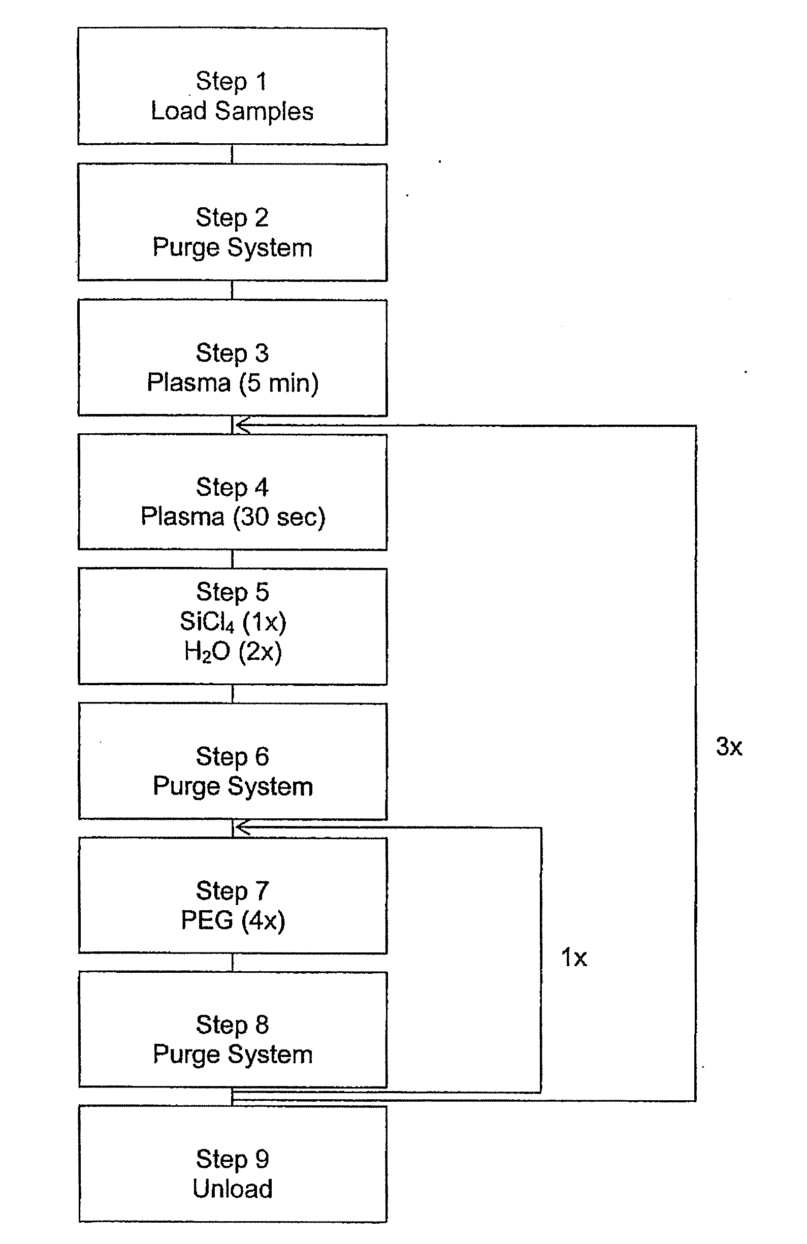
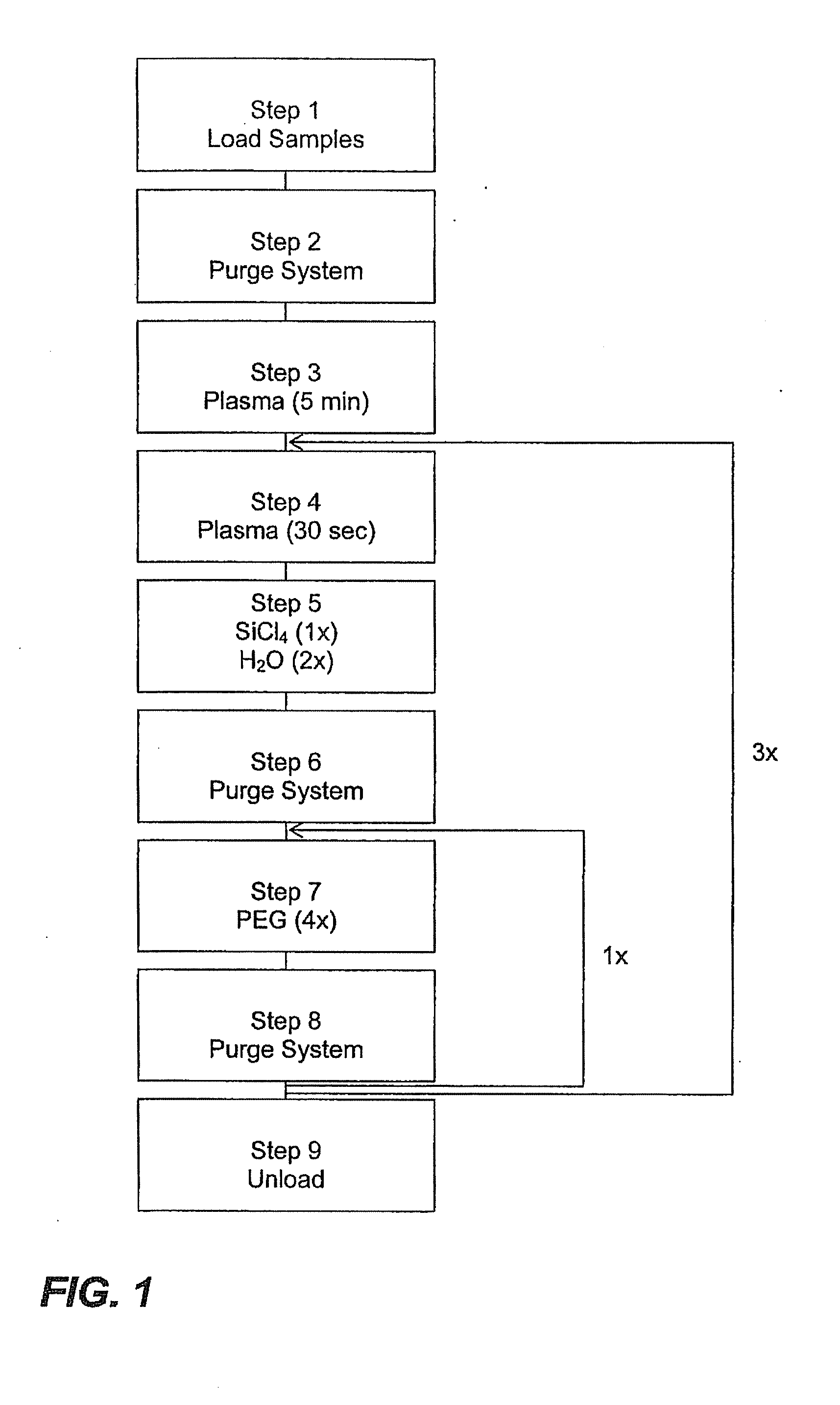
[0032]Substrates for PEG surface treatment included intraocular lenses and discs having dimensions of approximately 16.0 mm×1.0 mm. The PEG surface treatment was applied with a MVD 100 Molecular Vapor Deposition (MVD™) apparatus developed by Applied Microstructures Inc. (San Jose, Calif.). An illustrative example of the PEG treatment conditions are given in FIG. 1. Experimental conditions can be adjusted to increase or decrease the deposition of PEG.

[0033]A description of each of the process steps is given below.

[0034]Step 1: Samples are loaded onto stainless steel trays to secure the IOLs such that both of the optic surfaces are exposed to the PEG treatment. Each tray is capable of holding approximately 180 IOLs. The f...


PUM

PropertyMeasurementUnit
sizesaaaaaaaaaa
sizeaaaaaaaaaa
timeaaaaaaaaaa

Abstract

An intraocular lens with a hydrophilic polymer coating composition and methods for using same are provided. Specifically, a composition suitable for reducing tackiness in intraocular lens is provided wherein an acrylic intraocular lens is treated by vapor deposition with an alkoxy silyl terminated polyethylene glycol polymer composition. Methods for making an intraocular lens with a hydrophilic polymer coating are also provided.

Description

FIELD OF THE INVENTION[0001]The present invention relates to intraocular lens coating compositions and particularly to polyethylene glycol coatings to decrease the tackiness of soft acrylic intraocular lenses.BACKGROUND OF THE INVENTION[0002]The human eye is a highly evolved and complex sensory organ. It is composed of a cornea, or clear outer tissue which refracts light rays en route to the pupil, an iris which controls the size of the pupil thus regulating the amount of light entering the eye, and a lens which focuses the incoming light through the vitreous fluid to the retina. The retina converts the incoming light into electrical energy that is transmitted through the brain stem to the occipital cortex resulting in a visual image. In the perfect eye the light path from the cornea, through the lens and vitreous fluid to the retina is unobstructed. Any obstruction or loss in clarity within these structures causes scattering or absorption of light rays resulting in diminished visua...

Claims


Application Information

Patent Timeline
Patent Type & Authority Applications(United States)
IPC IPC(8): A61F2/16C23C16/00C08G77/02
CPCA61F2/1613A61L27/34A61L27/50A61L2430/16C08L71/02A61F2/16
Inventor LOWERY, MICHAEL D.HOFFMANN, LAURENT
Owner ABBOTT MEDICAL OPTICS INC
Learn More