Intake control for blower in vehicle wash system

a vehicle wash and blower technology, applied in drying machines, lighting and heating apparatus, drying machines with progressive movements, etc., can solve the problems of disadvantageous starting and stopping electric motors to achieve intermittent blower operation, not significantly addressing the intermittent nature of blower control systems, etc., to minimize possible damage to vehicle components, optimize the effect of flow and optimize drying performan

Inactive Publication Date: 2009-09-24
RYCO CANADA
View PDF19 Cites 9 Cited by
  • Summary
  • Abstract
  • Description
  • Claims
  • Application Information

AI Technical Summary

Benefits of technology

[0023]Using the blower and control system of the present invention, the amount of air flow delivered at any particular time may be varied dependent upon on one or more of several factors such as for example, the size of the vehicle to be dried, the type of the vehicle to be dried, the time of day and the associated cost of electricity at peak times during the day, and the outside ambient temperature. For example, it may be desirable to use a reduced airflow on convertible roofs and portions of pickup trucks in order to optimize drying performance and minimize possible damage to vehicle components.
[0024]In general, the ability to control the amount of airflow exiting the blower allows the flow to be optimized, thus extending the life of the blower components and also possibly reducing the noise generated by the blower. With the present invention, the amount of air being delivered by the blower may be accurately and easily controlled.

Problems solved by technology

However, such blower control systems do not significantly address the intermittent nature of vehicle traffic in a wash system.
It is not desirable to simply start and stop the blower motors as each vehicle passes into and out of the drying section.
It should be noted that starting and stopping an electric motor to achieve intermittent blower operation is disadvantageous.
For example, when an electric motor is started, it generates a high transient peak load and often a large amount of heat.
The high peak load may be undesirable as wash system operators may be charged more by their electrical utilities if there are peaks in their electricity demand, resulting in higher operational costs.
Also, frequently starting and stopping a blower motor decreases the life span of the motor, resulting in overall higher operating costs.
Additionally, the large amount of heat generated upon starting and stopping an electric motor limits the rate at which the motor may be started and stopped.
The amount of heat generated may be so significant that the blower cannot feasibly be started and stopped for each vehicle.
Furthermore, starting and stopping the blower motor is relatively slow and may limit the capacity of the drying section.
However, operating the motors continuously under load results in unnecessary wear and tear on the blowers and is not energy efficient, both factors resulting in increased operating costs.
A further disadvantage of continuously operating the blowers is that the blowers when being operated under load create a high noise level, particularly when no vehicle is present in the drying section to dampen the sound.
Previous attempts have been made to try to overcome some of these problems, but these methods are deficient in other ways.
For example, a variable speed motor (variable frequency drive motor) could be employed, but there are significant additional costs associated with such motors.
Additionally, variable speed motors may result in higher levels of electrical noise, compared to constant speed motors.
However, restricting or blocking the exit port creates an undesirable back-pressure that may reduce the life span of the blower components.
Consequently, placing the control mechanism at the exit port results in increased cost and places the control system and other blower components under increased stress.
However, there are significant disadvantages to the known inlet control devices, particularly in the manner in which the flow of air into an air blower is regulated.
Sustainable operation of known blower systems in wash systems at less than full capacity has proved difficult in the past.
For example, it is known to employ a valve plate as a valve mechanism to control the amount of air entering the blower; however this results in an unbalanced load being distributed over the impeller when the intake damper is not in the fully open or fully closed positions.
Similarly, it is known to employ louvers to block the air flow at the inlet, but this may disturb the uniformity of the air entering the blower when rotated to a partially open position and provide non-uniform input air flow on the impeller.
The louvers may also be required to be positioned a minimum distance from the impeller for optimal performance, particularly if rotated to a partially open position, rendering it difficult to design a compact blower system.
Additionally, known systems for drying vehicles do not accommodate variations in the types of vehicle being dried or distinguish between different part of the same vehicle, by varying the amount of air flow directed to the vehicle or specific parts thereof.

Method used


Image

  • Intake control for blower in vehicle wash system
  • Intake control for blower in vehicle wash system
  • Intake control for blower in vehicle wash system

Examples


Embodiment Construction

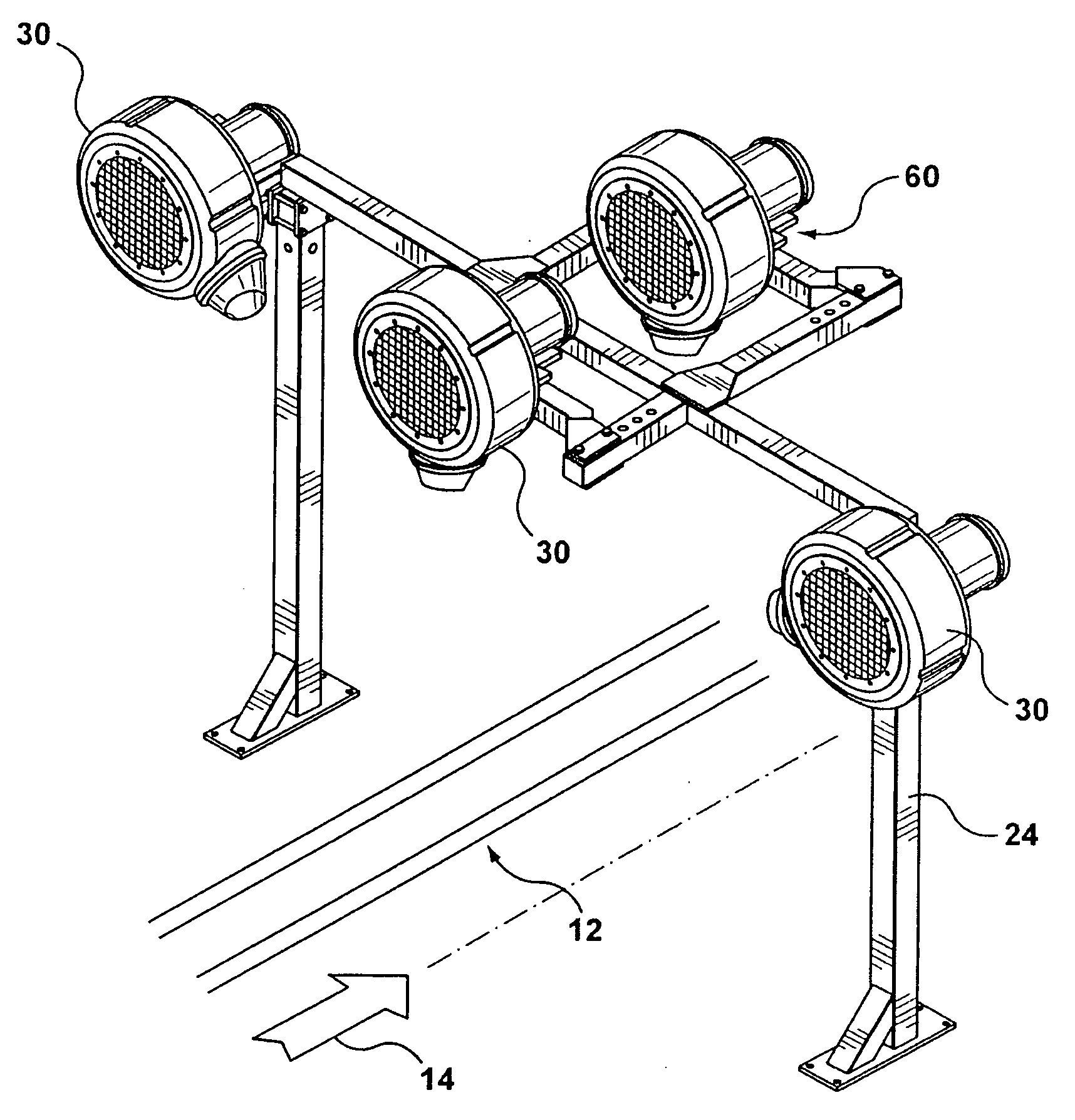
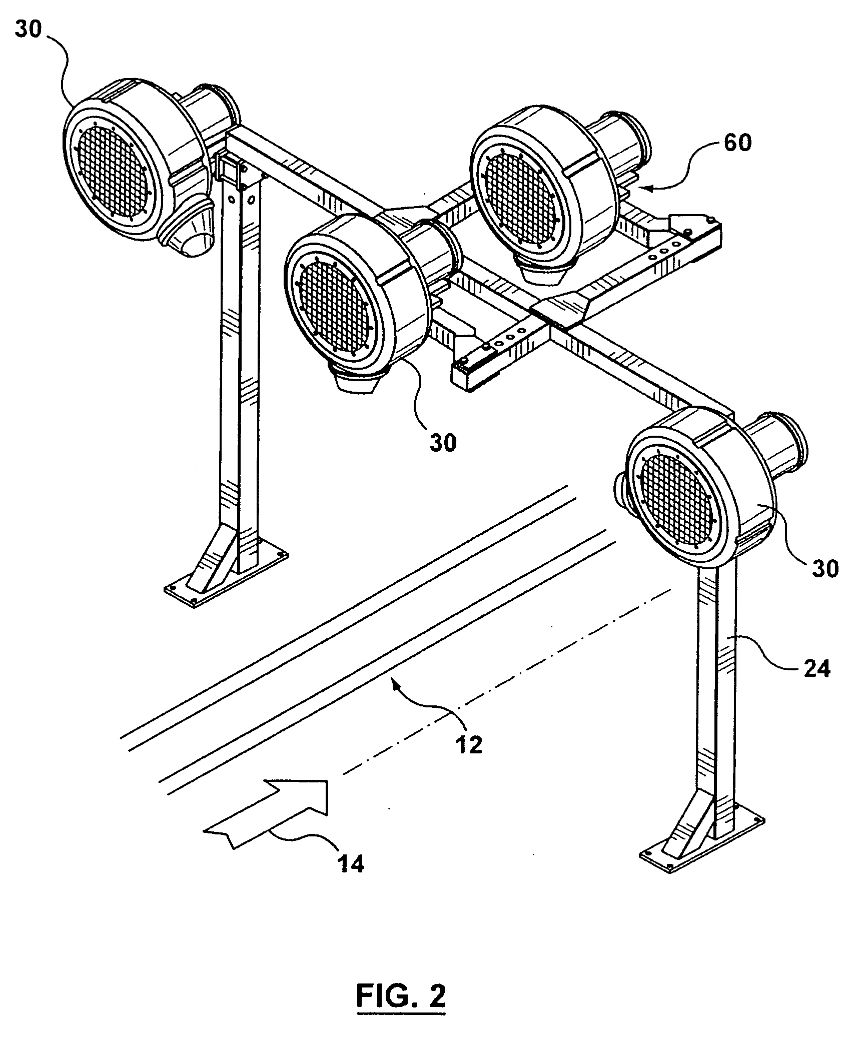
[0042]As referenced above, wash systems typically include a drying section to remove water from the vehicle surface, employing high velocity and high volume air, before the vehicle exits from the wash system. Illustrative examples disclosed hereinafter make reference to drying sections included in conveyor type wash systems, although the blower systems may also be applicable to rollover or other types of wash systems, with any required suitable modification.

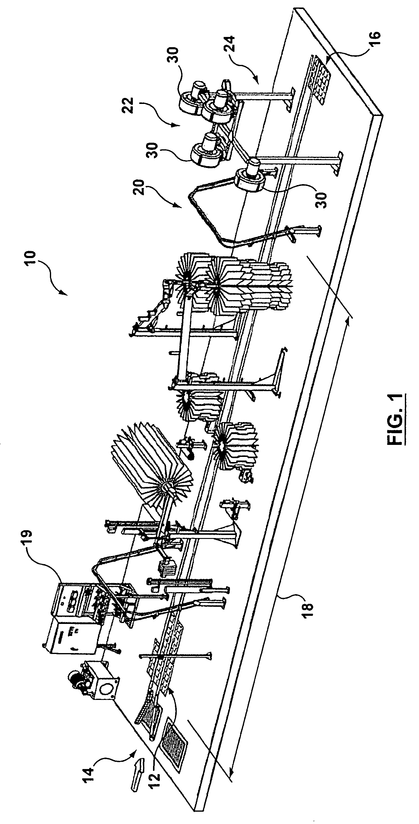
[0043]FIG. 1 illustrates an exemplary layout of a conveyor type wash system 10, the basic components of which are known in the art. Vehicles (not shown) may enter the wash system 10 at position 14 and may engage a conveyor system 12. The conveyor system 12 may provide for the movement of each vehicle as it proceeds through system 10 and ultimately exits at position 16.

[0044]Upon entry to wash system 10, a vehicle may pass through a wash section 18, which may be comprised of a series of brushes, as shown in FIG. 1. Alternatively, ...


PUM


Abstract

A vehicle wash system may have a drying station that may have a frame and a blower mounted on the frame. The blower may be used blowing liquid from the surface of a vehicle and may have a plenum with a cavity opening, an exit port, and an interior cavity. An impeller may be positioned inside the cavity, and when driven by a motor, may be operable to draw air into the cavity compress the air, and then emit an airflow from the plenum through the exit port. The blower may have an inlet region formed proximate the cavity opening and be in communication with the cavity. The inlet region may have a generally tubular inlet opening. A movement apparatus may be provided that is movable axially relative to the inlet opening to vary the size of the tubular inlet opening. The system may also include a sensor system operable to detect the presence and/or absence of a vehicle at drying station. A controller may be in communication with the sensor system and be operable to control the position of the movement device dependent upon the presence and/or absence of a vehicle to be dried.

Description

CROSS-REFERENCE TO RELATED APPLICATION[0001]This application claims priority from U.S. provisional application No. 61 / 064,688, filed Mar. 20, 2008, the contents of which are hereby incorporated herein by reference.FIELD OF THE INVENTION[0002]The present invention relates generally to blowers used in vehicle wash systems.BACKGROUND OF THE INVENTION[0003]Blowers are used in the drying section of vehicle wash systems. In both conveyor / tunnel-type wash systems and “roll-over” type vehicle wash systems, the drying section is typically located just before the vehicle exits the wash system. The drying section of a wash system may be comprised of a plurality of air blowers mounted on a frame. The air blowers are employed to dry the vehicles by forcing a stream of air over the surface of the vehicle. The stream of air may also be heated above ambient temperature: Such blowers are commonly referred to as “dryers” in vehicle wash systems.[0004]Each dryer typically has an outer housing or plenu...

Claims


Application Information

Patent Timeline
Patent Type & Authority Applications(United States)
IPC IPC(8): F26B21/00
CPCB60S3/002
Inventor MACNEIL, DANIEL J.
Owner RYCO CANADA
Why Eureka
Try Eureka