Boundary acoustic wave device

Active Publication Date: 2009-09-24
MURATA MFG CO LTD
View PDF10 Cites 29 Cited by
  • Summary
  • Abstract
  • Description
  • Claims
  • Application Information

AI Technical Summary

Benefits of technology

[0022]To overcome the problems described above, preferred embodiments of the present invention provide a boundary acoustic wave device which can effectively decrease a response intensity of a high order mod

Problems solved by technology

Thus, the surface acoustic wave device has a relatively complicated and large package structure.
However, the number of appearances of spurious responses is increased.
Thus, a filter characteristic of the surface wave device is not sufficiently improved.
However, if th

Method used


Image

  • Boundary acoustic wave device
  • Boundary acoustic wave device
  • Boundary acoustic wave device

Examples


Embodiment Construction

[0052]Specific preferred embodiments of the present invention will now be described with reference to the drawings.

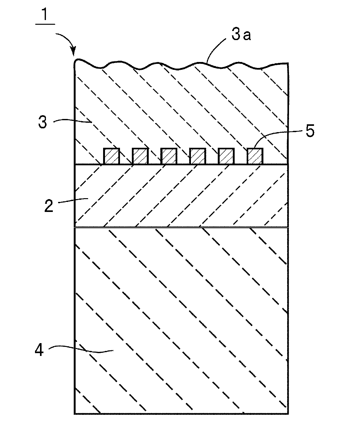
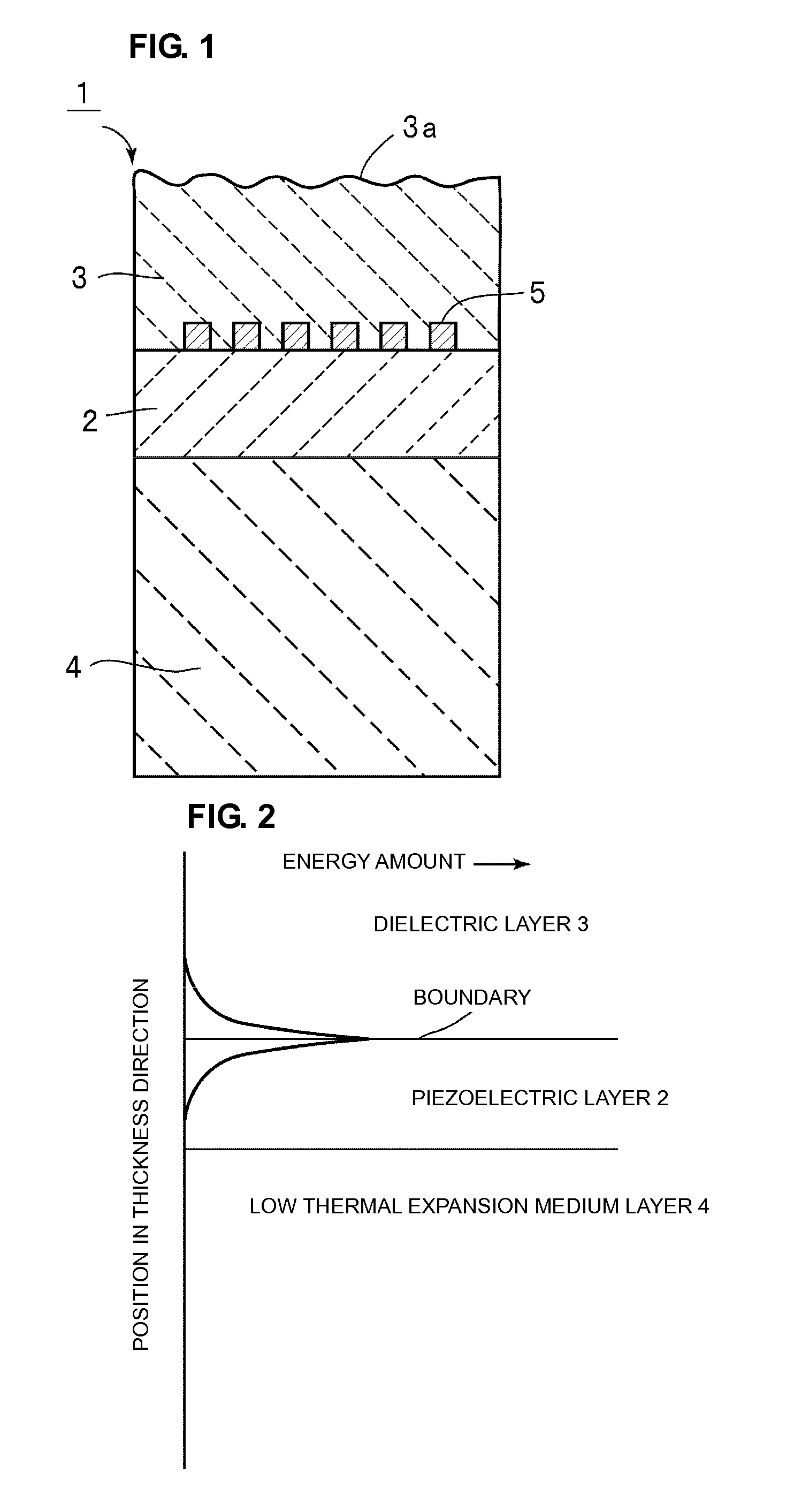
[0053]FIG. 1 is a schematic front cross-sectional view showing a boundary acoustic wave device according to a first preferred embodiment of the present invention.

[0054]A boundary acoustic wave device 1 includes a piezoelectric layer 2, a dielectric layer 3 laminated on the piezoelectric layer 2, a low thermal expansion medium layer 4 laminated on a surface of the piezoelectric layer 2 opposite to the surface on which the dielectric layer 3 is provided, and an IDT electrode 5 provided at the boundary between the piezoelectric layer 2 and the dielectric layer 3. The boundary acoustic wave device 1 of this preferred embodiment uses a SH boundary acoustic wave that propagates at the boundary between the piezoelectric layer 2 and the dielectric layer 3.

[0055]The piezoelectric layer 2 may preferably use piezoelectric single crystal, such as LiTaO3, LiNbO3, or quartz crystal, ...


PUM


Abstract

A boundary acoustic wave device includes an IDT electrode between a piezoelectric layer and a dielectric layer. A low thermal expansion medium layer made of a material having a linear thermal expansion coefficient less than that of the piezoelectric layer is laminated on a surface of the piezoelectric layer opposite to the boundary. Acoustic velocities of transversal waves in a boundary acoustic wave propagation direction at the piezoelectric layer, the dielectric layer, and the low thermal expansion medium layer satisfy Expression (1), and when λ represents a wavelength of the IDT electrode, (an acoustic velocity of a transverse wave at the dielectric layer)/λ satisfies Expression (2) as follows:
(acoustic velocity of transverse wave at dielectric layer)<(acoustic velocity of SH wave at piezoelectric layer)<(acoustic velocity of transverse wave at low thermal expansion medium layer)  Expression (1), and
(response frequency of boundary acoustic wave)<(acoustic velocity of transverse wave at dielectric layer)/λ<(response frequency of high order mode)  Expression (2).

Description

BACKGROUND OF THE INVENTION[0001]1. Field of the Invention[0002]The present invention relates to a boundary acoustic wave device used for a resonator or a band-pass filter, for example. More particularly, the present invention relates to a boundary acoustic wave device using a boundary acoustic wave that propagates at the boundary between a piezoelectric layer and a dielectric layer.[0003]2. Description of the Related Art[0004]Conventionally, a surface acoustic wave device has been widely used for a band-pass filter of a mobile phone or the like. For example, Japanese Unexamined Patent Application Publication No. 2004-186868 discloses a surface acoustic wave filter. FIG. 14 illustrates the structure of the filter.[0005]A surface acoustic wave filter 501 shown in FIG. 14 includes a piezoelectric layer 502 made of LiTaO3, and an IDT electrode 503 disposed on the piezoelectric layer 502. Sapphire 504 is attached to the back surface of the piezoelectric layer 502 opposite to a surface o...

Claims


Application Information

Patent Timeline
IPC IPC(8): H01L41/04
CPCH03H9/0222H03H9/02055
Inventor KANDO, HAJIME
Owner MURATA MFG CO LTD
Why Eureka
Try Eureka