

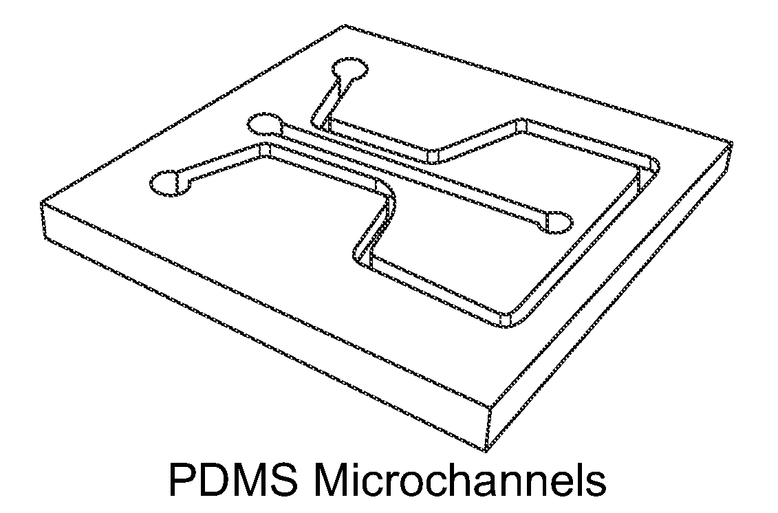
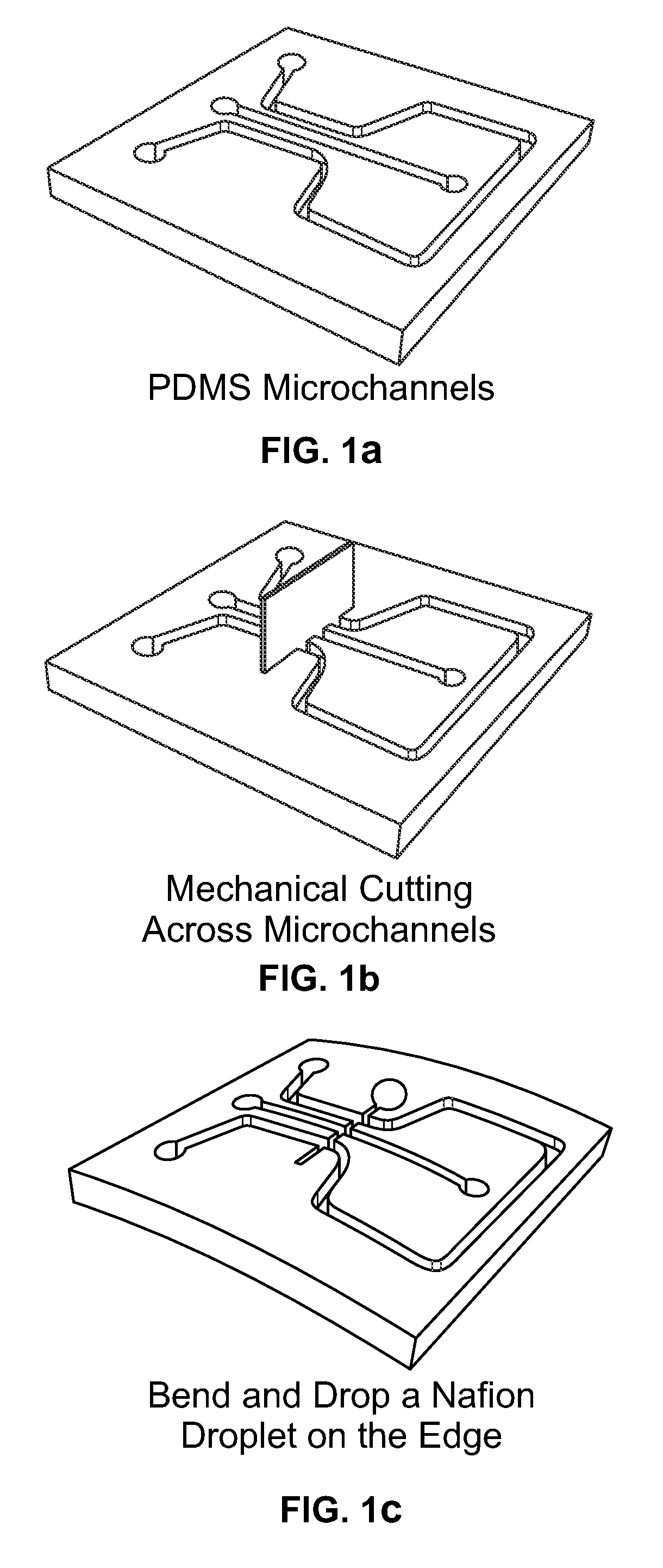
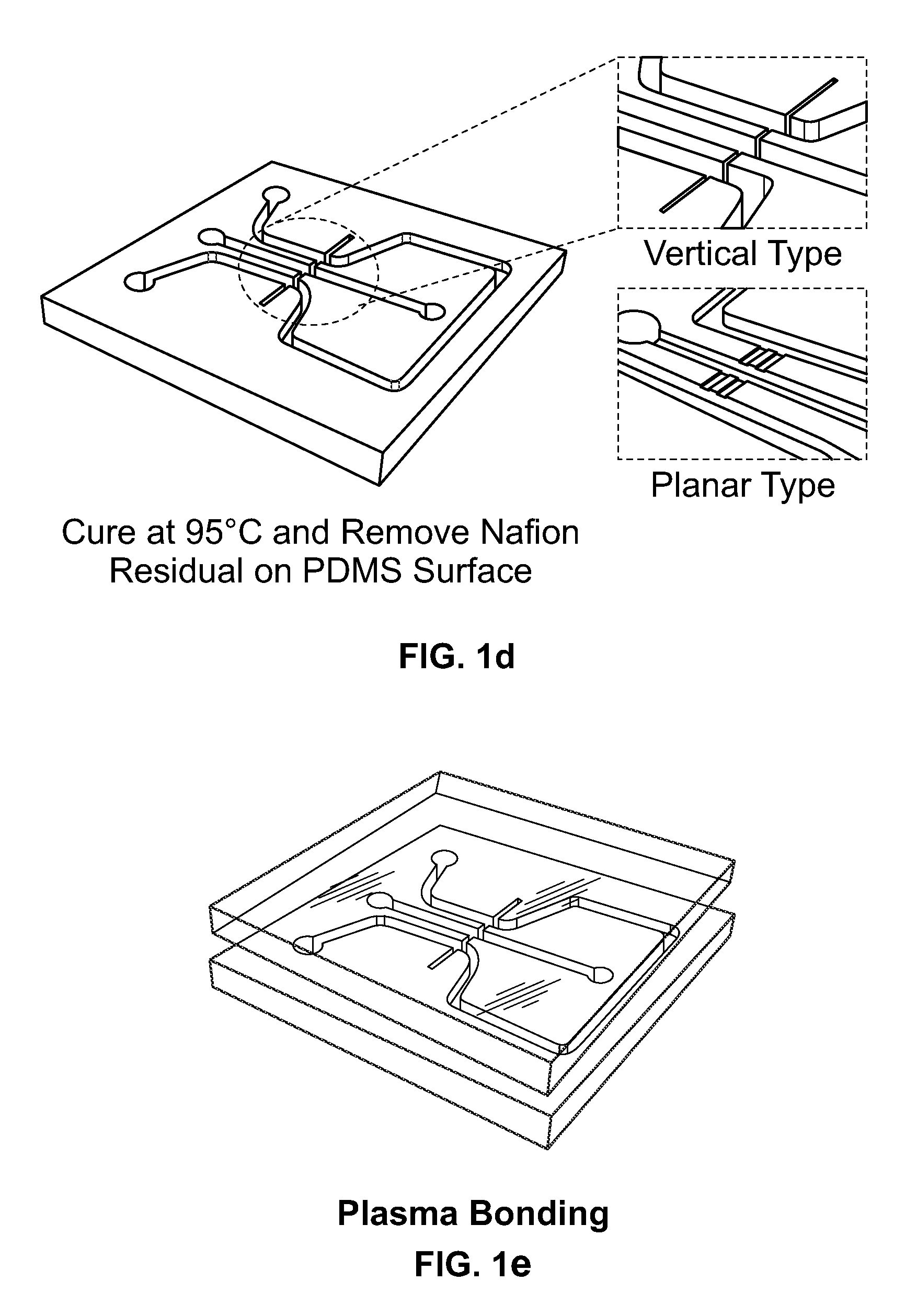
Methods for fabricating electrokinetic concentration devices
Image

Examples
example 1
[0202]The preconcentration factors of BODIPY disulfonate (Invitrogen) were measured using a device and methods of this invention. Three different solution concentrations were used. The concentrations used were 0.1 nM, 1 nM and 10 nM, in a 1 mM phosphate buffer solution. A DG device was used. Microchannels had dimensions of 100 microns width×10 micron depth as shown in FIG. 3a. The average tangential electric field was 50 V / cm. The fluorescent intensities were measured and analyzed as described in the method section herein above. Compared with its standard signal intensities (0.1 μM, 1 μM and 10 μM) the results showed that preconcentration factors of up to 1×10⁴ were achieved within 15 minutes. The preconcentration of β-phycoerythrin (β-PE) protein in the same device was measured. The preconcentration for two initial concentrations (1.67 nM and 16.7 pM) was measured and is shown in FIG. 3b. The 1×10⁴ preconcentration factors were achieved after 22 minutes. It...
example 2
Pressure Driven Ion / Protein Preconcentration Operation
[0203]Pressure driven preconcentration operations were conducted in devices of the present invention. FIG. 4 shows the preconcentration operation using external pressure fields. Operation voltages of 120 V were applied at both reservoirs causing a depletion voltage condition. External pressure flow was induced by a syringe pump (Harvard) at 35 nL / min from right to left. This tangential pressure flow (35 nL / min corresponding to 2.6 mm / sec in linear fluid velocity in this microchannel dimension) was at least 20 times faster than the electrokinetic velocity that can be obtained by the tangential field of 50 V / cm used in FIG. 3. The speed of preconcentration was enhanced approximately 2× compared to the speed shown in FIG. 3. The preconcentration reached 1×10⁴ within 7 minutes in FIG. 4.
example 3
High Performance Nanofluidic Pumping
[0204]The ionic concentration inside the ion depletion zone created near the membrane junction is so low that the solution can be considered desalted (below a few μM). In such a case the electric field inside this zone increases up to ˜kV / cm, even when an external electric field of 10 V / cm was applied. Thus the flow inside the zone experienced extremely high electric field and pushed the sample liquid all along the microchannel. This flow has reversed the pressure flow from opposite reservoir as shown in FIG. 5a. A syringe pump was connected to the right center reservoir with 0.1 μL / min flow. Initially, all liquid flew from right to left without external electric field. While keeping the 0 V at the right center reservoir, increasing the voltage at the left center reservoir initiated a concentration polarization near the membrane. After a certain voltage (60 V) was reached, the ion depletion zone was successfully created at the left hand side of th...
PUM
| Property | Measurement | Unit |
|---|---|---|
| Angle | aaaaa | aaaaa |
| Length | aaaaa | aaaaa |
| Volume | aaaaa | aaaaa |
Abstract
Description
Claims
Application Information
- IPC
- B01D61/42; B29C67/20; B01D63/00
- CPC
- B01L3/502707; B01L3/502761; B01L2200/0631; B01L2200/0652; B01L2300/0654; Y10T156/1002; B01L2400/0415; B01L2400/0421
- Inventors
- HAN, JONGYOON; KIM, SUNG JAE