Apparatus and Method for Agricultural Animal Wastewater Treatment

a technology for agricultural animals and wastewater treatment, applied in the direction of multi-stage water/sewage treatment, other chemical processes, separation processes, etc., to achieve the effect of facilitating biogas collection, reducing land area and upfront construction costs, and reducing land area

Inactive Publication Date: 2009-10-08
WILLIAMS SCOTT R
View PDF7 Cites 41 Cited by
  • Summary
  • Abstract
  • Description
  • Claims
  • Application Information

AI Technical Summary

Benefits of technology

[0041]The apparatus reduces the land area and upfront construction cost required for the system by subdividing an existing or newly constructed anaerobic lagoon to create an anaerobic digestion treatment zone below a sheet of material and a floating aquatic plant treatment zone above

Problems solved by technology

Agricultural animal waste disposal is a major problem.
While these CAFO's may be more productive and cost efficient, they come with the down side of manure management issues.
As the livestock industry has expanded, treatment of liquid manure waste using lagoon-spray field systems has come under increased public and governmental scrutiny due to environmental concerns over leaks, spills, odors, and ammonia emissions from the anaerobic lagoons as well as the high nutrient content of the lagoon effluent that is applied to spray fields.
Although considerable time, money, and effort has been put towards developing an EST in North Carolina, an EST candidate has yet to be developed or identified that meets the definition of an EST, nor has a candidate reached permittable status.
This has permanently curtailed the growth of the industry in North Carolina until a solution to the problem is found.
One of the main problems with many of the prior art examples listed above and the industries approach to the problem in general is that the focus has tended to be on technologies and processes that are more appropriate for large scale waste treatment operations. e.g. solids separation, aeration, heating etc.
Waste treatment technologies that can meet the “technically feasible” requirements of an EST have existed for years but are too expensive and complicated to construct and operate at the farm level.
They are expensive to build, are too complicated operate without significant oversight, and have high energy requirements.
Another problem with many of the prior art examples listed above, and the industries approach to the problem in general is that they have tended to focus on year round treatment of waste.
Treatment systems utilizing year round treatment and frequent or continuous discharge are mo

Method used


Image

  • Apparatus and Method for Agricultural Animal Wastewater Treatment
  • Apparatus and Method for Agricultural Animal Wastewater Treatment
  • Apparatus and Method for Agricultural Animal Wastewater Treatment

Examples


first embodiment

—FIGS. 1A, 1B, 1C, 1D, 2A

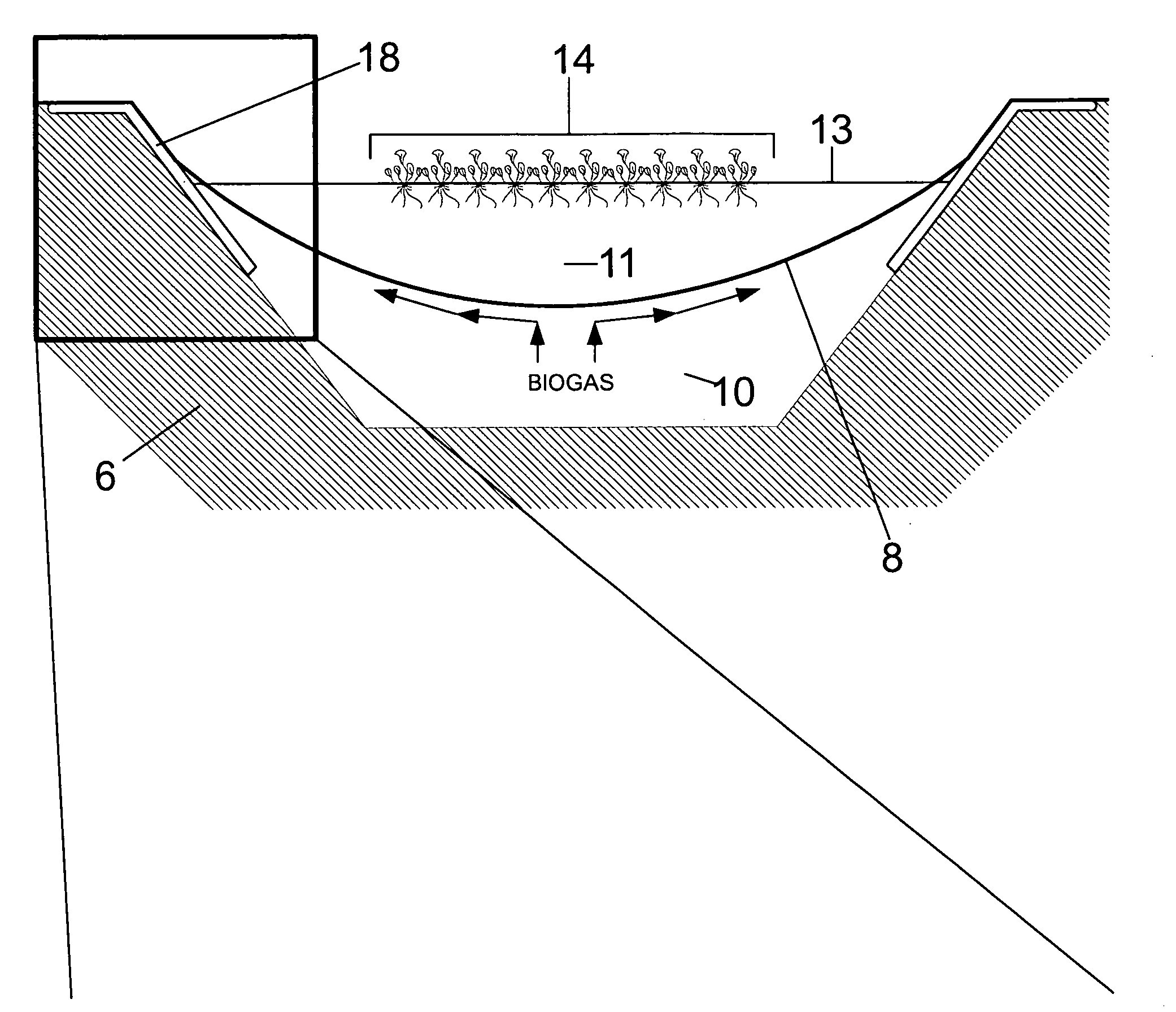
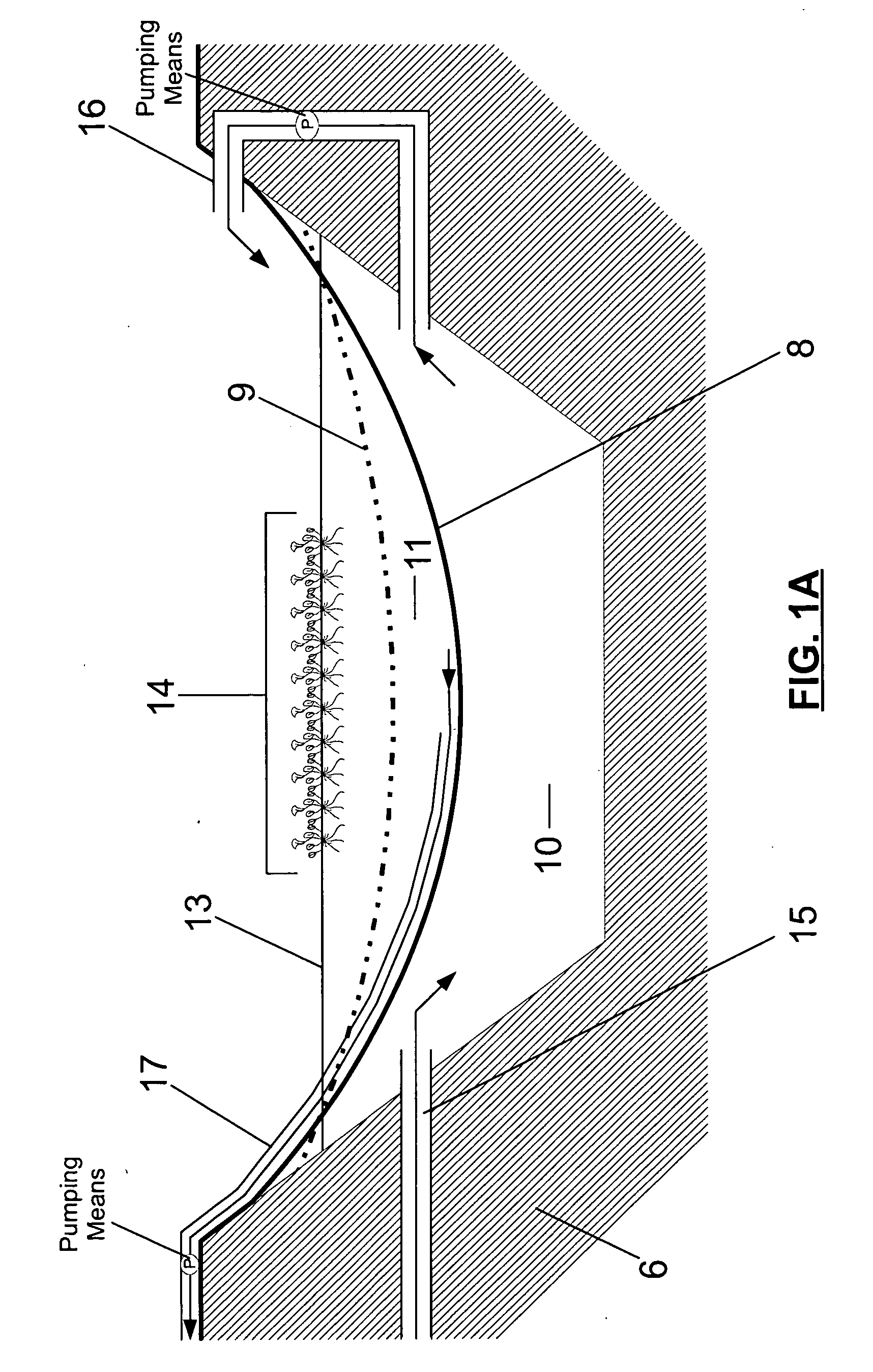
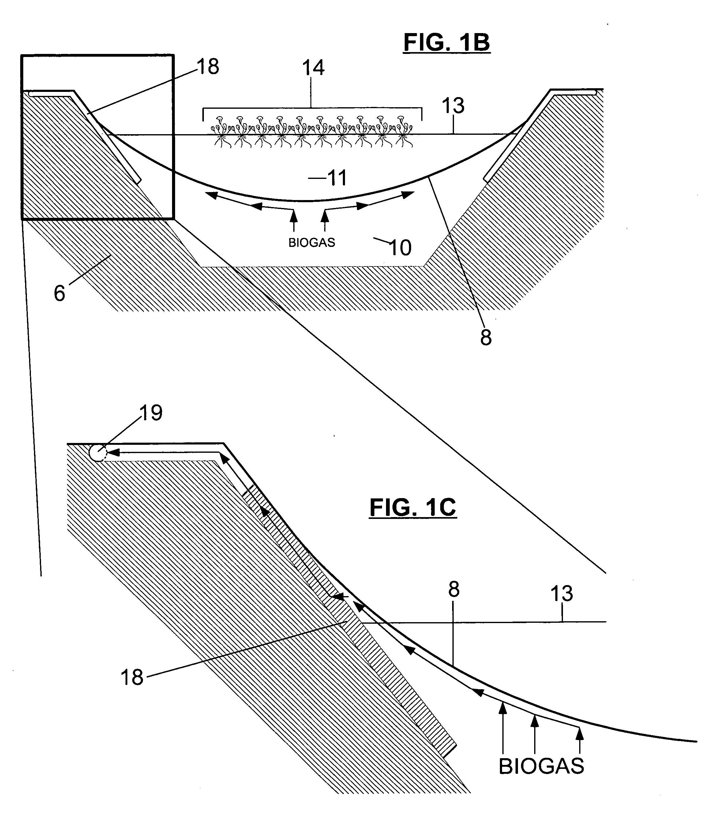
[0084]A first embodiment of the apparatus and method is illustrated by FIGS. 1A-1D and FIG. 2A. FIG. 1A illustrates how a sheet of material 8 subdivides an existing or newly constructed anaerobic lagoon 6 to create an anaerobic digestion treatment zone 10 below the sheet of material 8 and a floating aquatic plant treatment zone 11 above the sheet of material 8. Both treatment zones are sufficiently sized to allow for temporary storage. The sheet of material 8 is flexible and impermeable. The sheet of material's 8 flexibility is illustrated in FIG. 1A with an alternate position of the sheet of material 9 that results from changes in the liquid volume of the two treatment zones. FIG. 1A also illustrates several conveyance means and the direction of flow through the treatment zones. FIGS. 1B-1D illustrate how the sheet of material 8 diverts biogas evolving from anaerobic digestion treatment 22 in the anaerobic digestion treatment zone 10 to a biogas collection ...

second embodiment

Description—FIGS. 1A, 1B, 1C, 1D, 2B

[0125]A second embodiment of the apparatus and method is illustrated by FIGS. 1A-1D and FIG. 2B and is very similar to the first embodiment with the exception being the absence of specificities related to the the useful purposes for biogas and floating aquatic plant biomass. FIG. 1A illustrates how a sheet of material 8 subdivides an existing or newly constructed anaerobic lagoon 6 to create an anaerobic digestion treatment zone 10 below the sheet of material 8 and a floating aquatic plant treatment zone 11 above the sheet of material 8. Both treatment zones are sufficiently sized to allow for temporary storage. The sheet of material 8 is flexible and impermeable. The sheet of material's 8 flexibility is illustrated in FIG. 1A with an alternate position of the sheet of material 9 that results from changes in the liquid volume of the two treatment zones. FIGS. 1B-1D illustrate how the sheet of material 8 diverts biogas evolving from anaerobic diges...

third embodiment

Description—FIGS. 1A and 2C

[0127]A third embodiment of the apparatus and method is illustrated by FIGS. 1A and 2C and is very similar to the second embodiment with the exception being that this embodiment does not incorporate a biogas collection means or useful purposes for biogas or floating aquatic plant biomass. FIG. 1A illustrates how a sheet of material 8 subdivides an existing or newly constructed anaerobic lagoon 6 to create an anaerobic digestion treatment zone 10 below the sheet of material 8 and a floating aquatic plant treatment zone 11 above the sheet of material 8. Both treatment zones are sufficiently sized to allow for temporary storage. The sheet of material 8 is flexible and impermeable. The sheet of material's 8 flexibility is illustrated in FIG. 1A with an alternate position of the sheet of material 9 that results from changes in the liquid volume of the two treatment zones. FIG. 2C is a flow chart illustrating the method of this embodiment that the apparatus of t...


PUM

PropertyMeasurementUnit
Areaaaaaaaaaaa

Abstract

One embodiment of an apparatus and method for treating agricultural animal wastewater that costs less to build, is easy to operate, and requires little energy input. The method employs natural systems for wastewater treatment; an initial anaerobic digestion treatment followed by batch floating aquatic plant treatment. The batch floating aquatic plant treatment of effluent and subsequent batch discharge provides increased control of the treatment process. Opportunistic collection and use of biogas and floating aquatic biomass results in additional benefits. The apparatus reduces the cost and land area required for the system by subdividing a lagoon into an anaerobic digestion treatment zone below the apparatus and a floating aquatic plant treatment zone above the apparatus. In addition, the apparatus is disposed in the lagoon in such a way that it facilitates the collection of biogas evolving from anaerobic digestion treatment beneath the apparatus by diverting it to areas to be collected.

Description

CROSS-REFERENCED TO RELATED APPLICATIONS[0001]This application claims the benefit of provisional patent application No. 61 / 043,117 filed Apr. 7, 2008 by the present inventor.FEDERALLY SPONSORED RESEARCH[0002]Not ApplicableSEQUENCE LISTING OR PROGRAM[0003]Not ApplicableBACKGROUND OF THE INVENTION[0004]1. Field[0005]This application generally relates to an apparatus and method for wastewater treatment and more specifically to an apparatus and method incorporating natural systems for treatment and management of agricultural animal wastewater.[0006]2. Prior Art[0007]Agricultural animal waste disposal is a major problem. Over the past several decades, increased demand for meat and dairy products has facilitated the rapid growth of the commercial livestock industry. The increased demand and subsequent growth of the industry has led to the utilization of more centralized higher capacity farming operations. These farming operations are sometimes referred to as concentrated animal feeding op...

Claims


Application Information

Patent Timeline
IPC IPC(8): C02F3/32
CPCC02F3/28C02F3/327C02F2103/20Y02E50/343C12M21/04C12M23/18C02F2209/006Y02W10/37Y02E50/30Y02W10/10
Inventor WILLIAMS, SCOTT REID
Owner WILLIAMS SCOTT R
Why Eureka
Try Eureka