Apparatus and method for fluorescence imaging and tomography using spatially structured illumination

a technology of spatial structure and apparatus, applied in the field of imaging systems, can solve the problems of not teaching thorwirth how to adapt the disclosed arrangement, tromberg not teaching how to minimize excitation radiation, etc., and achieve the effect of reducing excitation radiation

Inactive Publication Date: 2009-10-08
BRUKER BIOSPIN
View PDF5 Cites 23 Cited by
  • Summary
  • Abstract
  • Description
  • Claims
  • Application Information

AI Technical Summary

Benefits of technology

[0011]Another embodiment of a method according to the invention also concerns a method for performing depth sectioned fluorescence imaging of a turbid sample including a fluorescent turbid medium. The method uses an apparatus for quantitative modulated fluorescence imaging, the apparatus including projection optics with a first optical axis, to expose the turbid sample to a periodic pattern of excitation radiation to provide depth-resolved discrimination of fluorescent structures within the turbid medium; an image capture module, including a second optical axis and a detection beam path, to receive a data image from the sample; and a signal processor to transform the data image from the sample, spatially filter the transformed data image from the sample, and reconstruct the filtered, transformed data image from the sample. The method includes steps of: inclining the first optical ax

Problems solved by technology

However, Tromberg does not teach how to minimize the excitation radiation from reaching the detection beam path.
However, Thor

Method used


Image

  • Apparatus and method for fluorescence imaging and tomography using spatially structured illumination
  • Apparatus and method for fluorescence imaging and tomography using spatially structured illumination
  • Apparatus and method for fluorescence imaging and tomography using spatially structured illumination

Examples


first embodiment

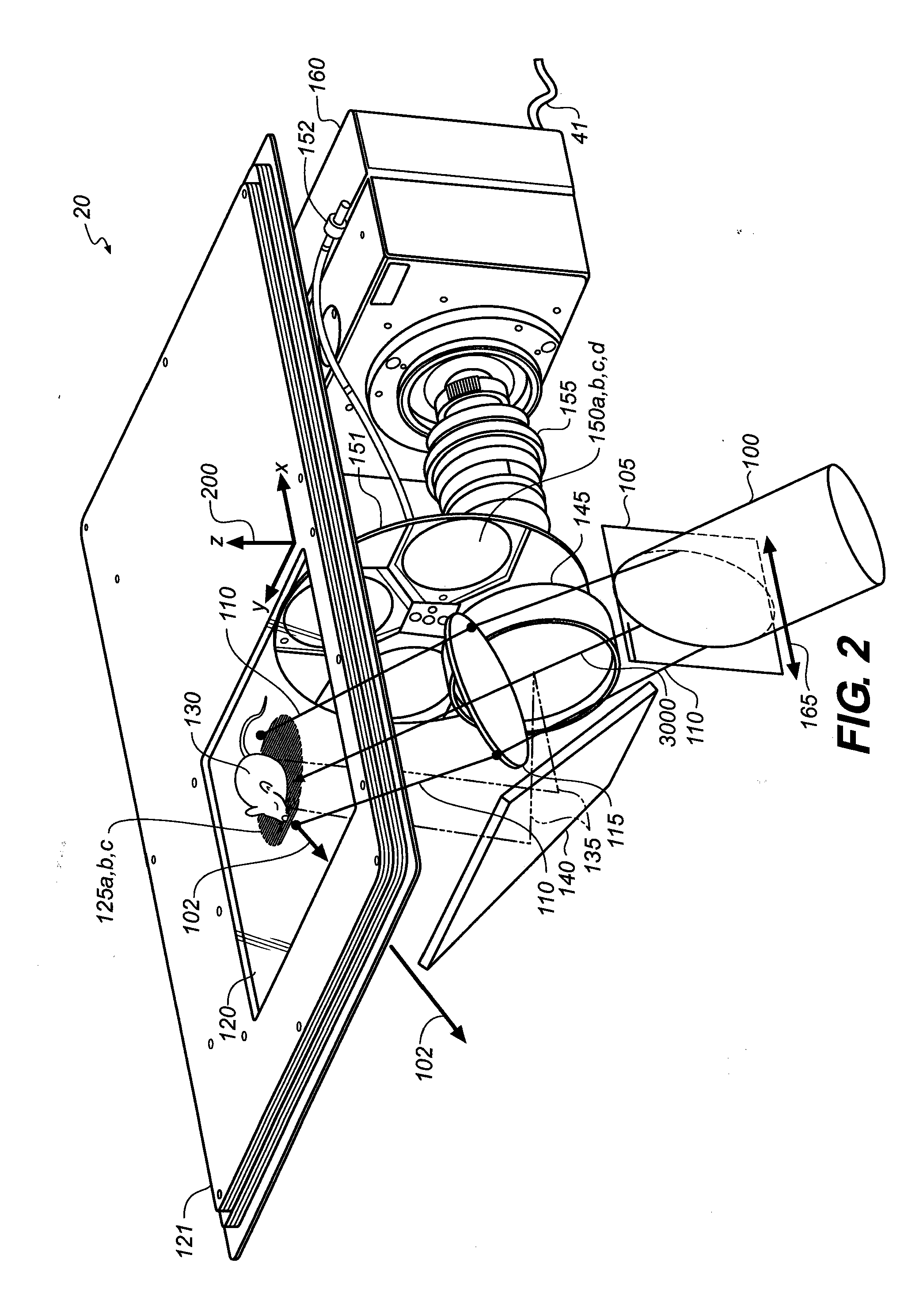
[0042]FIG. 2 shows a cutaway perspective view of components of image capture module 20 in accordance with the present invention wherein spatially modulated excitation radiation is delivered from direction “a” using projection optics comprised of a non-telecentric Scheimpflug lens system 115. The X-Y-Z coordinate system is defined 200. Excitation radiation 100 is transmitted through a one-dimensional spatial modulation grid 105. The spatial modulation grid is coplanar with the object plane of a non-telecentric Scheimpflug lens system 115. In the embodiment shown, the non-telecentric Scheimpflug lens system includes a single lens group as indicated; however, generally more than one lens group may comprise a non-telecentric Scheimpflug lens system. The spatial modulation grid is configurable or movable to produce a plurality of phases that shift along the direction indicated by arrow 165. Lens system 115 delivers the spatially modulated excitation radiation through a beam path 110 to t...

second embodiment

[0050]FIG. 12 shows a cutaway perspective view of components of the image capture module 21 in accordance with the present invention wherein spatially modulated excitation radiation is delivered from direction “a” using projection optics including a non-telecentric Scheimpflug lens system 115. This embodiment is similar to the embodiment shown in FIG. 2, however an additional spatial modulation grid 106 and non-telecentric Scheimpflug lens system 116, mirror-symmetric to spatial modulation grid 105 and non-telecentric Scheimpflug lens system 115 across the X-Z plane bisecting the platen 120, are included for delivery of excitation radiation from direction “b” in an additional step. FIGS. 13A, 13B and 13C show cutaway diagrammatic views of the image capture module 21 configured according to FIG. 12. FIGS. 13A, 13B and 13C are similar to FIGS. 7A, 7B and 7C.

[0051]FIG. 14 shows a cutaway perspective view of the image capture module 21 of FIG. 12 wherein spatially modulated excitation r...

third embodiment

[0053]FIG. 17 shows a cutaway perspective view of components of the image capture module 22 in accordance with the present invention wherein spatially modulated excitation radiation is delivered from direction “a” using projection optics including a doubly telecentric Scheimpflug lens system 215. This embodiment is similar to the embodiment shown in FIG. 12, except the non-telecentric Scheimpflug lens systems 115 and 116 have been replaced with doubly telecentric Scheimpflug lens systems 215 and 216, respectively. In the embodiment shown, the doubly telecentric Scheimpflug lens systems each include two lens groups as indicated; however, generally more than two lens groups may comprise a doubly telecentric Scheimpflug lens system. By “doubly telecentric”, it is meant that the lens system provides both object space telecentricity and image space telecentricity. The lens system delivers the spatially modulated excitation radiation through a beam path 210 to the surface of the platen 12...


PUM


Abstract

An imaging system is disclosed for imaging an object. More specifically, an improvement is disclosed in an imaging system enabling depth sectioned fluorescence imaging in a turbid medium, such as human or animal tissue, in such a manner as to substantially minimize the excitation radiation from reaching the detection beam path. The imaging system includes an arrangement of the excitation radiation source such that the optical axis of the source is inclined relative to the optical axis of the camera, the optical plane of the source and the optical plane of the object are subject to a Scheimpflug condition provided by projection optics, and the angle of inclination of the source is selected such that the excitation radiation incident upon the object is reflected in such a way that substantially minimizes excitation radiation from reaching the detection beam path.

Description

CROSS REFERENCE TO RELATED APPLICATIONS[0001]Reference is made to, and priority is claimed from, commonly assigned, copending provisional U.S. patent application Ser. No. 61 / 043,188, filed Apr. 8, 2008 by Gilbert Feke, entitled APPARATUS AND METHOD FOR FLUORESCENCE IMAGING AND TOMOGRAPHY USING SPATIALLY STRUCTURED ILLUMINATION, which is incorporated by reference.FIELD OF THE INVENTION[0002]The invention relates generally to the field of imaging systems, and more particularly to the imaging of objects. More specifically, the invention relates to an improvement in an apparatus and method enabling depth sectioned fluorescence imaging in a turbid medium, such as human or animal tissue, in such a manner as to substantially minimize the excitation radiation from reaching the detection beam path.BACKGROUND OF THE INVENTION[0003]It is well known in the art to use structured illumination to carry out fluorescence-based molecular imaging in turbid media. U.S. Publication 2006 / 0184043 by Tromb...

Claims


Application Information

Patent Timeline
IPC IPC(8): G01N21/64
CPCG01N21/6456G01N2021/1782G01N2021/1787A61B2576/00A61B5/0071A61B5/0077G01N2201/0635
Inventor FEKE, GILBERTVOCI, LAURIE L.
Owner BRUKER BIOSPIN
Why Eureka
Try Eureka