Variable-flux motor drive system

a technology of variable-speed motors and drive systems, applied in the direction of motor/generator/converter stoppers, dynamo-electric converter control, transportation and packaging, etc., can solve the problems of high heat loss of pm motors at low speed, field-weakening control must be carried out, and the efficiency of superposed excitation currents deteriorate, so as to prevent a braking force from being applied and protect the system. the effect of safety

Active Publication Date: 2009-10-22
KK TOSHIBA
View PDF12 Cites 83 Cited by
  • Summary
  • Abstract
  • Description
  • Claims
  • Application Information

AI Technical Summary

Benefits of technology

[0038]According to the above-mentioned and other aspects of the present invention, demagnetization is carried out when the variable-flux motor drive system must...

Problems solved by technology

The IM motor generates magnetic flux by an excitation current from a stator, and therefore, has a technical problem of causing a loss when passing the excitation current.
The switching frequency of a switching element in the inverter of the PM motor is high, and therefore, the PM motor causes a large loss and heat at low speed because the loss is dependent on a current value.
On the other hand, if an induced voltage is high, field-weakening control must be carried out.
In this case, a superposed excitation current deteriorates efficiency.
On the other hand, for the variable speed control of an electric train or an electric vehicle, the PM motor has operating points at which it shows inferior efficiency compared to the conventional IM motor.
For the inverter, increases in the current capacity and...

Method used


Image

  • Variable-flux motor drive system
  • Variable-flux motor drive system
  • Variable-flux motor drive system

Examples


first embodiment

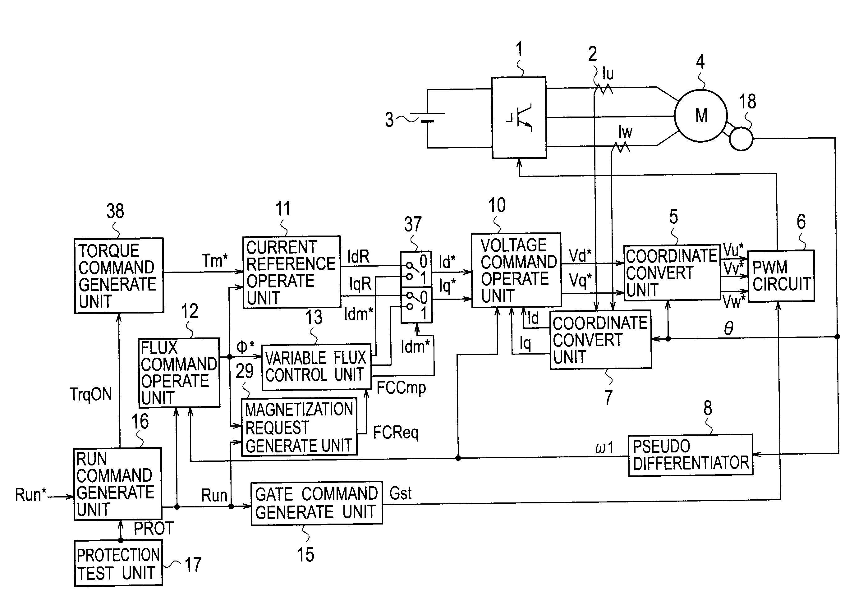
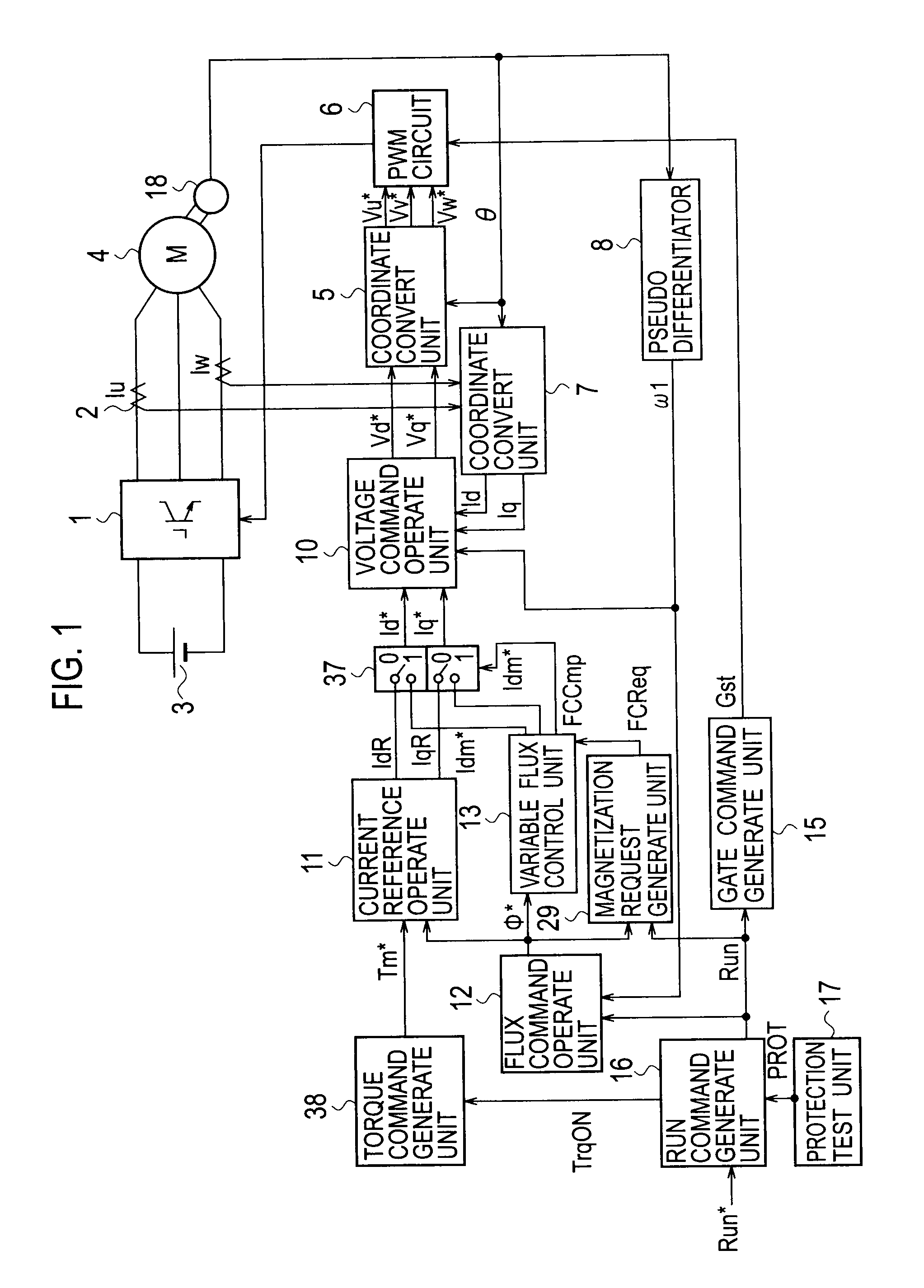
[0097]FIG. 1 is a block diagram showing a variable-flux motor drive system according to the first embodiment of the present invention. First, a main circuit including a variable-flux motor 4 of the drive system will be explained. An inverter 1 inverts DC power from a DC power source into AC power, which is supplied to the variable-flux motor 4. Currents Iu and Iw supplied to the variable-flux motor 4 are detected by a current detector 2 and are converted by a coordinate convert unit 7 into a D-axis current Id and a Q-axis current Iq, which are input to a voltage command operate unit 10. The voltage command operate unit 10 outputs a D-axis voltage command Vd* and a Q-axis voltage command Vq* to a coordinate convert unit 5, which converts them into three-phase voltage commands Vu*, Vv*, and Vw* to be input to a PWM circuit 6. The PWM circuit 6 controls ON / OFF of switching elements of the inverter 1 according to a gate command Gst from a gate command generate unit 15. A rotational angl...

second embodiment

[0167]FIG. 10 is a block diagram showing a variable-flux motor drive system according to the second embodiment of the present invention. The second embodiment differs from the first embodiment shown in FIG. 1 in that a magnetization request generate unit 29 generates a preliminary magnetization request flag FCReq0 to be supplied to a torque command generate unit 38 instead of the magnetization request flag FCReq to be supplied to the variable flux control unit 13 and that the torque command generate unit 38 receives, in addition to a torque permission flag TrqON, the preliminary magnetization request flag FCReq0 and a magnetization completion flag FCCmp and generates, in addition to a torque command Tm*, a magnetization request flag FCReq. Namely, the torque command generate unit 38 prepares the torque command Tm* to reduce torque when magnetizing a variable magnet, and after reducing torque, provides the variable flux control unit 13 with the magnetization request flag FCReq. Accor...

third embodiment

[0177]FIG. 13 is a block diagram showing a variable-flux motor drive system according to the third embodiment of the present invention. The third embodiment differs from the first embodiment shown in FIG. 1 in that it additionally has a modulation factor operate unit 61 and a field-weakening control unit 62, an output signal from the field-weakening control unit 62 being supplied to a magnetization request generate unit 29. As a result, the magnetization request generate unit 29 generates a magnetization request based on a modulation factor of an inverter 1. The same elements as those of FIG. 1 are represented with the same reference marks, to omit repetitive explanations.

[0178]In FIG. 13, a DC voltage Vdc of the inverter 1 is detected by a DC voltage detector 60 and is supplied to the modulation factor operate unit 61. The modulation factor operate unit 61 receives the DC voltage Vdc and D- and Q-axis voltage commands Vd* and Vq* from a voltage command operate unit 10. Based on the...


PUM


Abstract

A variable-flux motor drive system including a permanent-magnet motor including a permanent magnet, an inverter to drive the permanent-magnet motor, and a magnetize device to pass a magnetizing current for controlling flux of the permanent magnet. The permanent magnet is a variable magnet whose flux density is variable depending on a magnetizing current from the inverter. The magnetize device passes a magnetizing current that is over a magnetization saturation zone of magnetic material of the variable magnet. This system improves a flux repeatability of the variable magnet and a torque accuracy.

Description

TECHNICAL FIELD[0001]The present invention relates to a variable-flux motor drive system.BACKGROUND TECHNOLOGY[0002]Instead of conventional induction motors (IM motors), permanent-magnet synchronous motors (PM motors) that are highly efficient and are expected to be miniaturized and noise-reduced are spreading. For example, the PM motors have become used as drive motors for electric trains and electric vehicles.[0003]The IM motor generates magnetic flux by an excitation current from a stator, and therefore, has a technical problem of causing a loss when passing the excitation current.[0004]On the other hand, the PM motor is a motor having a rotor provided with a permanent magnet whose flux is used to output torque, and therefore, has no such a problem of the IM motor. However, the PM motor induces, due to the permanent magnet, a voltage depending on the number of revolutions. In the application field of electric trains and vehicles that involves a wide range of rotational speeds, a ...

Claims


Application Information

Patent Timeline
IPC IPC(8): H02P6/08H02K21/12
CPCH02K1/2766H02K15/03H02P21/0089H02P21/02H02P21/06H02P23/0095H02K21/042H02P21/10H02P23/14H02K1/276Y02T10/643H02P23/28Y02T10/64
Inventor YUUKI, KAZUAKISAKAI, KAZUTOMOCHIKAWA, HIROSHI
Owner KK TOSHIBA
Why Eureka
Try Eureka