Compact tilt and vibration sensor and method for manufacturing the same

a technology of tilt and vibration and sensor, which is applied in the direction of acceleration measurement using interia forces, instruments, material analysis, etc., can solve the problems of sensor useful life reduction sensor motion sensitivity degrade, etc., and achieve high motion sensitivity, high durability, and high performance

Inactive Publication Date: 2009-10-29
G DEVICE CORP
View PDF8 Cites 18 Cited by
  • Summary
  • Abstract
  • Description
  • Claims
  • Application Information

AI Technical Summary

Benefits of technology

[0009]It is, therefore, a principal object of the present invention to provide a compact tilt and vibration sensor, which has a high performance, such as high motion sensitivity, a high durability and a high reliability, and a method for manufacturing the same.
[0010]Another object of the present invention is to provide a compact tilt and vibration sensor, which can be mass produced to be supplied at a reasonable price and enables a detection of a tilt or vibration in multi directions, and a method for manufacturing the same.

Problems solved by technology

First, if the air with moisture may enter the hollow portion of a sensor case, the sensor is likely to be affected by the viscosity of the moisture, and the movement of the conductive sphere as a movable electrode gets slower, and also the sensor is likely to be affected by the viscosity of the moisture, which is attached to the surfaces of a fixed electrode and the sphere in the hollow portion, and the movement of the conductive sphere has hysteresis characteristics, which causes the motion sensitivity of the sensor to be degraded.
Second, in a reflow process of surface mounting operation that uses SMI, heating causes the flux as a binder in the solder paste formed on the printed circuit board by screen printing to be evaporated, and the resulting vapor or the volatile portion contains harmful gases, such as chlorine, which decompose the electrode and the sphere, thereby if such gases may enter the sensor hollow portion, the surfaces of the electrodes and the sphere are decomposed by the oxidative effect or fluxing action of the harmful gases, and the motion sensitivity of the sensor to be degraded, and moreover, the useful life of the sensor is reduced.
Third, a temperature rise in the hollow portion of a sensor causes the temperature of the gases in the hollow portion to rise, which increases the potential risk of breakage of the sensor case due to the pressure of the gases in addition to the reduced thickness of the sensor case for downsizing.
Fourth, the downsizing reduces the distance between the electrodes and the sphere, which in turn reduces the electrical insulation distance, thereby any attachment of moisture or impurities to the electrodes or other elements causes an insulation resistance to be considerably reduced, and an arc discharge that damages the electrodes to be easily generated, and the durability and performances of the sensor to be adversely affected.
Fifth, because the volume of the hollow portion of the sensor case is considerably reduced, it is difficult to arrange electrode plates that are made of conductive metal plates such as copper plates and have a common property in the hollow portion.
Sixth, if the sphere is charged with a static electricity, which is generated by the friction contact between the sphere of a metallic ball and the inner wall surface of the sensor case, which is an insulator, an attraction or repulsion arises therebetween, which may cause irregular motion of the sphere.

Method used


Image

  • Compact tilt and vibration sensor and method for manufacturing the same
  • Compact tilt and vibration sensor and method for manufacturing the same
  • Compact tilt and vibration sensor and method for manufacturing the same

Examples


Embodiment Construction

[0032]Now, an embodiment of the present invention will be explained in detail below by way of the following examples.

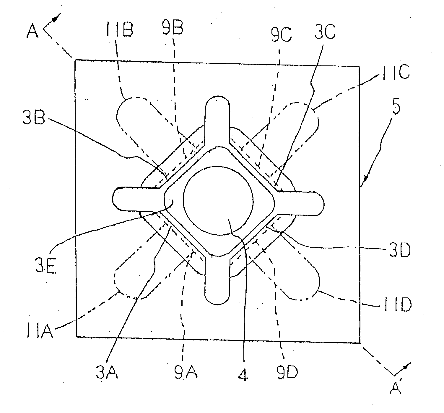
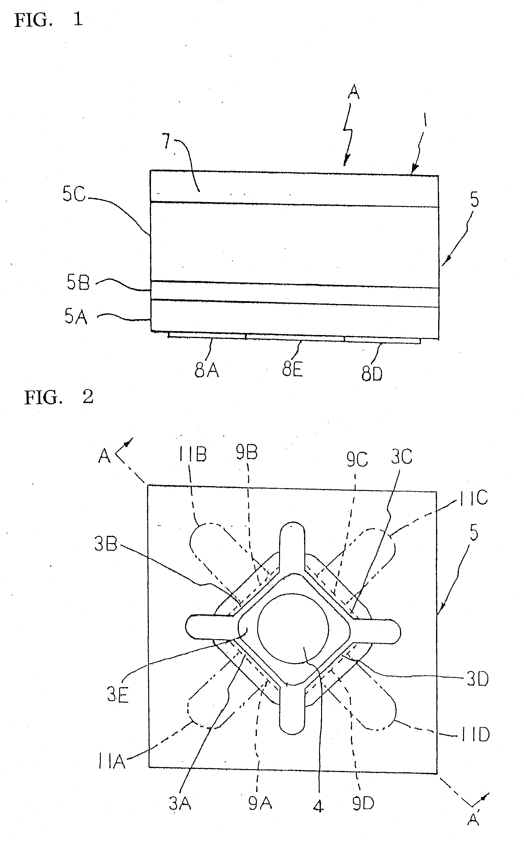
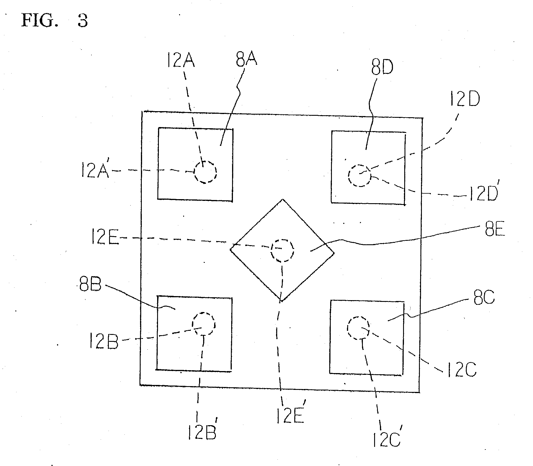
[0033]FIGS. 1 to 4 show a tilt and vibration sensor A as one example of the present invention: FIG. 1 is a front view of the sensor; FIG. 2 is a plan view of a case body of the sensor; FIG. 3 is a bottom view of the sensor; and FIG. 4 is a vertical cross-sectional view taken along the line A-A′ of FIG. 2 showing the sensor. In these drawings, the reference numeral 1 designates a non-conductive case of the sensor A, the reference numeral 2 designates a hollow portion of the case, the reference numerals 3A, 3B, 3C, 3D, and 3E designate electrodes, and the reference numeral 4 designates a conductive sphere, which is freely movably accommodated in the hollow portion.

[0034]The sensor case 1 includes a case body 5 that is formed of a non-conductive material such as fine ceramics having a high gas barrier property and a high heat resistance for blocking any gas transmission ...


PUM

PropertyMeasurementUnit
widthaaaaaaaaaa
lengthaaaaaaaaaa
heightaaaaaaaaaa

Abstract

Provided are a tilted vibration sensor incorporating a plurality of electrodes and a conductive spherical body which is turned on and off by the moving displacement of the spherical body, and which may be remarkably reduced in size and may have high performance and high operating sensitivity, high durability, and high reliability; and a method of manufacturing the sensor. The case (1) of the sensor comprises a case body (5) formed of a non-conductive material having such excellent gas-barrier property and heat resistance that can stop the transmission of gases which affects on the on/off operation of the sensor due to the moving displacement of the conductive spherical body (4) and a cover body (7) sealing airtight the opening part (6) of the case body. In the method of manufacturing the vibration sensor, moisture and particulate impurities affecting the on/off operation are removed from the hollow part (2) of the case (1), and the hollow part is evacuated.

Description

TECHNICAL FIELD[0001]The present invention relates to a compact tilt and vibration sensor, which has a plurality of electrodes arranged in a non-conductive case and a conductive sphere movably received in the non-conductive case so that a moving displacement of the sphere due to a tilt or a vibration of the case causes the sensor to be turned on / off to detect the tilt or the vibration.BACKGROUND ART[0002]Sensors of this type are widely used today to be incorporated in home appliances, electronic products, and other various products and devices to detect a tilt or a vibration of the products and devices instead of mercury sensors, which use mercury, a harmful substance, as a movable electrode, but recently, as the devices in which the sensors are used are continuously downsized and the demands to mount the sensors into high-tech electronics of a compact size, such as digital camera and cell phone, have drastically increased, the level of the market demand for more downsizing, higher ...

Claims


Application Information

Patent Timeline
Patent Type & Authority Applications(United States)
IPC IPC(8): G01H11/06H01R43/00
CPCG01C9/10H01H1/66Y10T29/49117H01H35/144H01H2009/0292H01H35/025H01H35/02
Inventor SHIMASE, TERUO
Owner G DEVICE CORP
Why Eureka
Try Eureka