Catheter

a catheter and catheter technology, applied in the field of catheters, can solve the problems of increasing the diameter and the flexibility of the connecting region, affecting the efficiency of insertion, and sometimes difficult to treat the lesion, and achieve the effect of favorable insertion efficiency

Inactive Publication Date: 2009-10-29
KANEKA CORP
View PDF14 Cites 18 Cited by
  • Summary
  • Abstract
  • Description
  • Claims
  • Application Information

AI Technical Summary

Benefits of technology

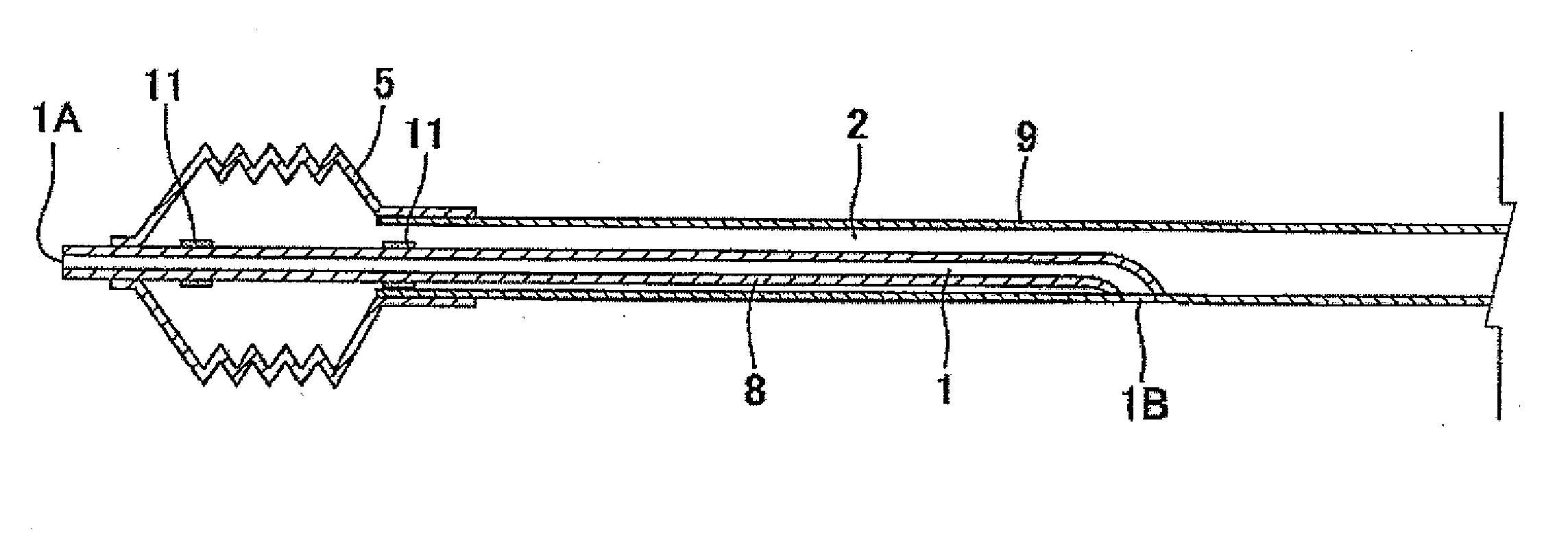
[0027]The present invention provides a catheter having a coaxial shaft structure in the region of guide wire lumen, having pressure transmission efficiency transmitting the force applied to the catheter proximal end side efficiently to the distal side or distal end of the catheter, and having favorable insertion efficiency into stricture site while the deformation of the internal and external shafts for the coaxial structure in a nested pattern is prevented, without deterioration in the flexibility of catheter, and also in the enlargement-contraction response of the balloon in the case of a balloon catheter and in injection response in the case of an injection catheter.

Problems solved by technology

In the cases of a lesion significantly higher in the degree of stricture or of chronic complete obstruction, it is occasionally difficult to treat the lesion by advancing the guide wire beyond the stricture site.
Because the OTW catheter has a guide wire lumen over the entire length of the balloon catheter, it is often used for sending a guide wire to the lesion that prohibits passage of the guide wire, but the operation of withdrawing the balloon catheter while leaving the guide wire in the lesion is rather complicated and causes problems.
However, such a catheter demands an adhesive or sleeve parts for connection of the first and second tubular parts, which lead to increase in the diameter and decrease of the flexibility of the connecting region, and thus, was not sufficiently favorable in the convenience of inserting the catheter into bent blood vessel.
However, the adhesion region, where the internal and external tubular parts are bonded to each other, is lower in flexibility, and thus, it was difficult to advance the catheter by pushing the adhesion region through a bent blood vessel.
The catheter also had a problem that the second lumen in the adhesion region was vulnerable to deformation when the adhesion region was bent, and the enlargement-contraction response of the expandable balloon was lower.
However, also in this prior art, the region where the external and internal tubes are connected is lower in flexibility, lowering the efficiency of sending the region through a bent blood vessel.
In addition when the region is bent, the expandable lumen in the region deforms more easily, undesirably lowering the enlargement-contraction response of the catheter.

Method used


Image

  • Catheter
  • Catheter
  • Catheter

Examples


example 1

[0123]A tubular parison (internal diameter: 0.43 mm, external diameter: 0.89 mm) was prepared by extrusion molding of a polyamide elastomer (PEBAX7033SA01, Elf Atochem); and a balloon having a straight-tube external diameter of 3.0 mm, a straight-tube length of 20 mm, a length of the tapered regions at the distal and proximal end sides of 5 mm, and a length of the connecting regions at the distal and proximal end sides of 5 mm was prepared by biaxially stretching blow molding of the parison.

[0124]A tube (internal diameter: 0.43 mm, external diameter: 0.56 mm) was prepared by extrusion molding of high-density polyethylene (HY540, Japan Polychem Corporation). The high-density polyethylene tube was cut into pieces of 46 mm and 254 mm in length. One end of the 46 mm-cut tube was expanded to an internal diameter of 0.58 mm, and one end of the 254 mm-cut tube was inserted into the expanded region and fused by heating, to give an internal shaft. The heat-fused region represents the project...

example 2

[0129]A tube having the crosssectional shape shown in FIG. 15 (diameter of inflation lumen 2a: 0.86 mm, thickness: 0.14 mm, diameter of each inflation lumen 2b: 0.06 mm) was prepared with a polyamide elastomer (PEBAX7233SA01 Elf Atochem) by extrusion molding. A balloon catheter was prepared in a similar manner to Example 1, except that the tube prepared was cut into pieces of 5 mm in length, and a tube prepared with a polyamide elastomer (PEBAX7233SA01, Elf Atochem) by extrusion molding (internal diameter 0.72 mm, external diameter 0.86 mm) was connected to both ends thereof by heat fusion to form a diameter-reducing protuberance.

example 3

[0130]A balloon catheter was prepared in a similar manner to Example 1, except that the core material 26B having the shape shown in FIG. 22 (diameter of large cylindrical region 27C: 0.41 mm, diameter of small cylindrical region 27d: 0.16 mm) was used in preparing the diameter-reducing protuberance.


PUM


Abstract

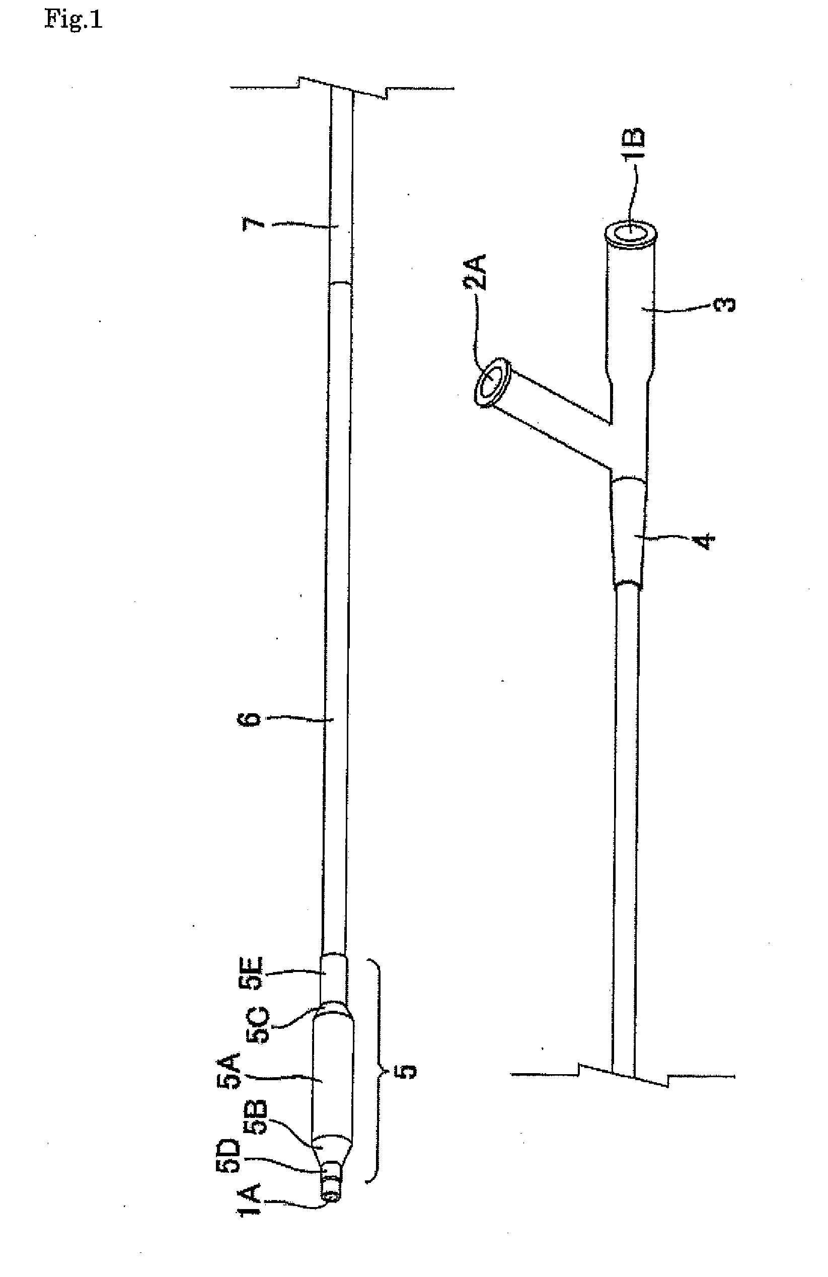
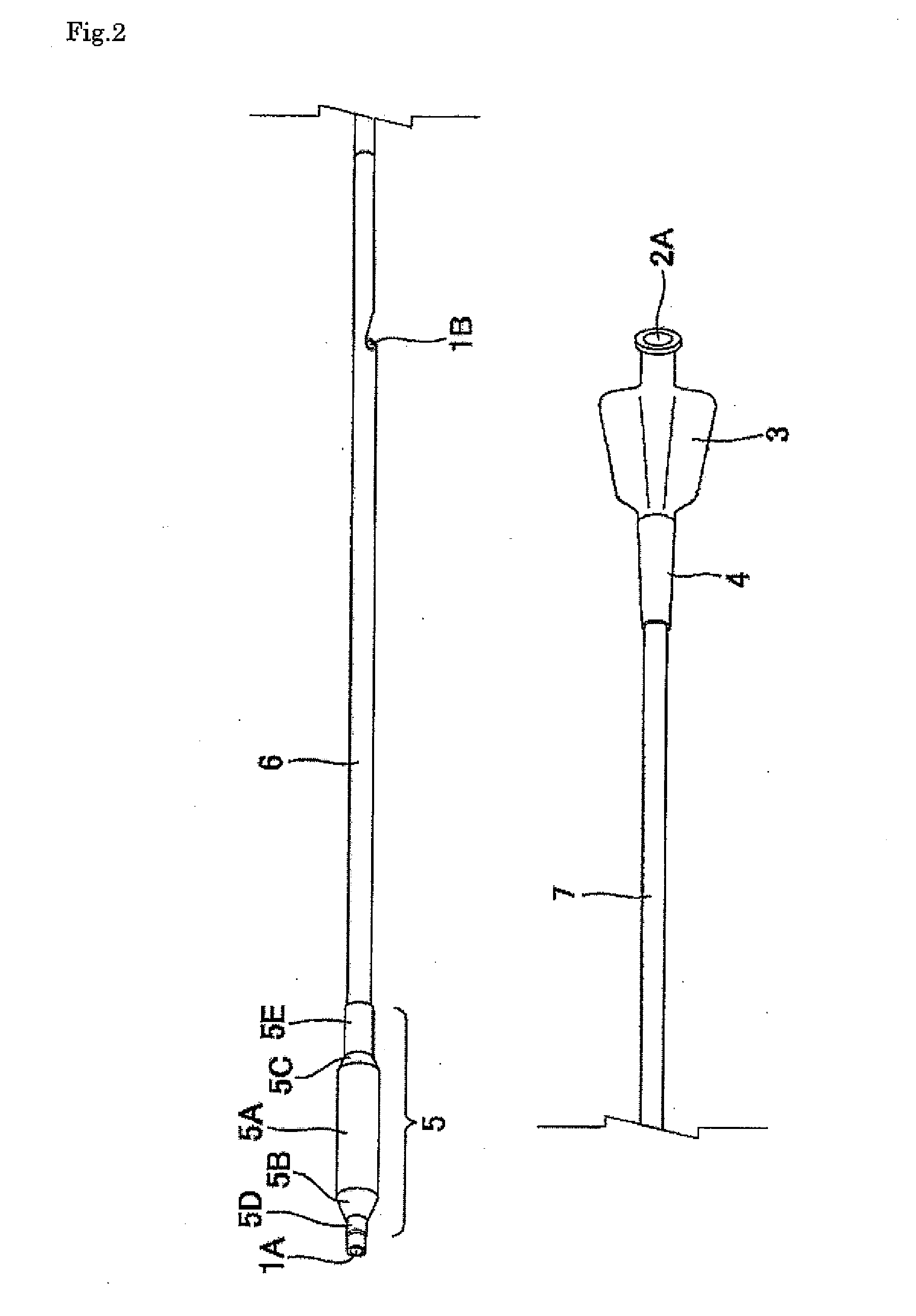
A catheter having a proximal shaft and a distal shaft each having a proximal end section and a distal end section. The distal end of the proximal shaft and the proximal end of the distal shaft are connected to each other, a catheter holding hub is connected to the proximal end of the proximal shaft, and a part of at least the distal shaft is constructed from an inner shaft and an outer shaft coaxially surrounding the inner shaft. The inner shaft is extended out from the outer shaft to the distal side. The lumen of the inner shaft forms a guidewire lumen. The catheter has a means for restricting relative movement of the outer shaft and the inner shaft occurring when pressing force exceeding a predetermined level is applied to the catheter.

Description

TECHNICAL FIELD[0001]The present invention relates to a catheter for use in medical application, and in particular, to a balloon catheter for use in peripheral angioplasty and percutaneous transluminal angioplasty (PTA, or percutaneous transluminal coronary angioplasty, PTCA) during coronary angioplasty, valve repair, or the like, a penetrating catheter for penetration through a stricture site, an injection catheter allowing administration of a treatment substance to local site, and the like.BACKGROUND ART[0002]Percutaneous transluminal angioplasty has been practiced widely, for example, for treatment of stricture or obstruction of vascular lumen by enlargement and for recovery or improvement of blood flow in coronary and peripheral blood vessels. The balloon catheter used in the percutaneous transluminal angioplasty has a shaft and a balloon expandable and contractable freely by regulation of its internal pressure that is connected to the terminal region of the shaft, and the shaft...

Claims


Application Information

Patent Timeline
Patent Type & Authority Applications(United States)
IPC IPC(8): A61M25/10A61M25/16A61F2/958
CPCA61M25/0023A61M25/0029A61M25/0032A61M2025/0183A61M25/10A61M2025/0037A61M25/0043
Inventor SHIMADA, TAMOTSUTAKATERA, MASAYUKINISHIDE, TAKUJI
Owner KANEKA CORP
Why Eureka
Try Eureka