Process for production of a dental component and arrangement of such component

a technology for dental components and dental implants, which is applied in dental prosthetics, dental surgery, impression caps, etc., can solve the problems of insufficient technical material strength of components produced in such ways, failure to meet other dental-related requirements, and difficult to avoid gradients and tensions, etc., to achieve cost reduction, increase homogeneity, and increase cost

Inactive Publication Date: 2009-11-05
NOBEL BIOCARE SERVICES AG
View PDF11 Cites 17 Cited by
  • Summary
  • Abstract
  • Description
  • Claims
  • Application Information

AI Technical Summary

Benefits of technology

[0015]Further, embodiments of the invention make possible new manufacturing processes for individual production of, e.g., crowns and bridges. The production becomes more cost effective. For example, it has been shown that production of ceramic dental components in accordance with the invention can be carried out with 40% cost reduction compared with other current production methods and apparatus.
[0016]Embodiments of the invention also propose a new gel casting method based on acrylate instead of amide. As a result, embodiments of the invention can acheive increased homogeneity and reduced deformation during the pressing function. Substantial versatility with respect to shape and size, as well as individual components or large series of components, can be provided. Requirements for the monomer used are in accordance with the above, e.g., reduced toxicity. The monomer can be water soluble and capable of being subjected to thermically induced polymerization. Further, the monomer can provide sufficient strength and does not cause adverse effects during ceramic sludging. The temperature threshold for the gel slurry can also be high; e.g., over 70° C.

Problems solved by technology

Research has shown that components produced in such ways do not have sufficient technical material strength and fail to meet other dental-related requirements.
However, implementation of the pressing process has the disadvantage that it is difficult to avoid gradients and tensions are often built into the components that are made using such a process.

Method used


Image

  • Process for production of a dental component and arrangement of such component
  • Process for production of a dental component and arrangement of such component
  • Process for production of a dental component and arrangement of such component

Examples


Embodiment Construction

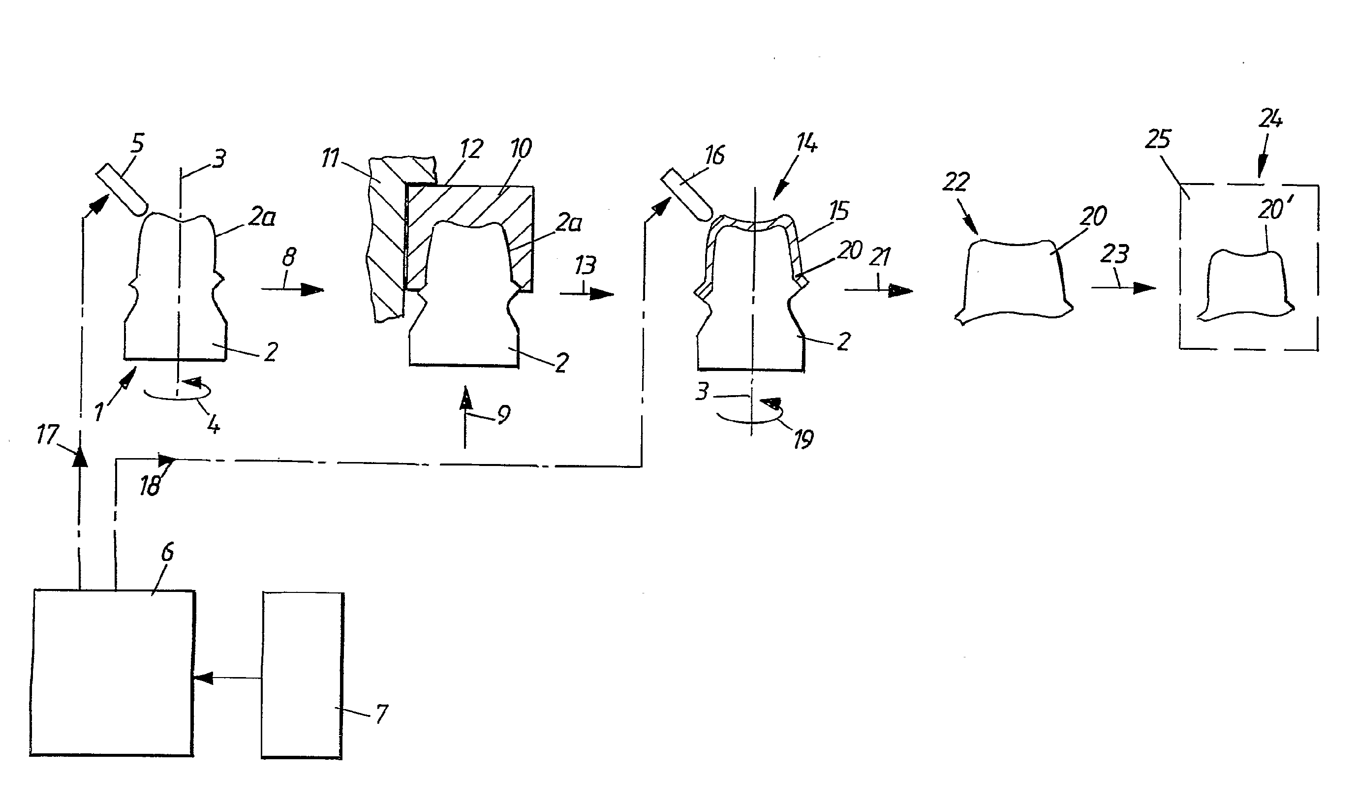
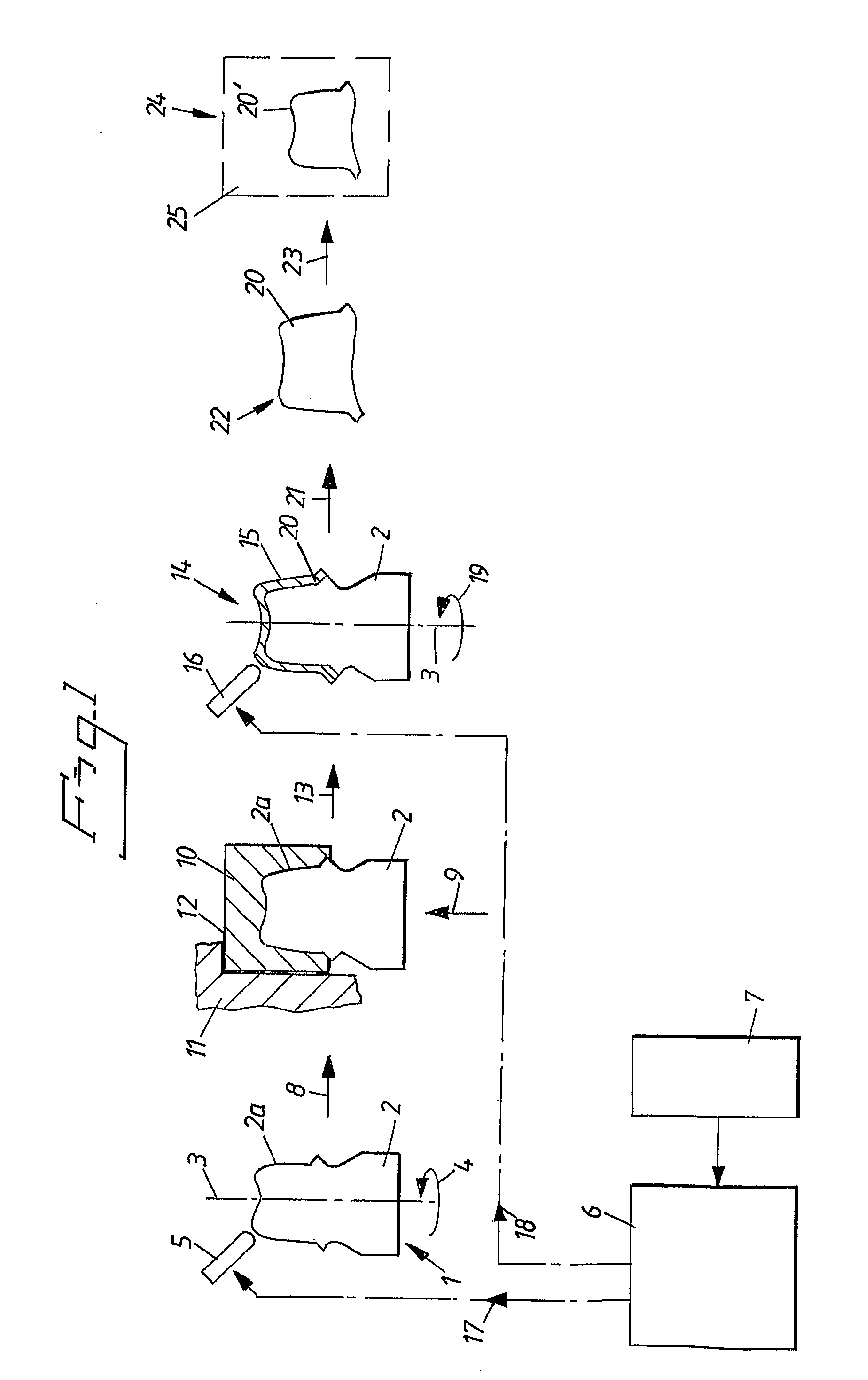
[0024]FIG. 1 illustrates various steps in crown production according to the fully automated system PROCERA® and embodiments of the invention. A symbolically represented cast station is designated by 1. A first cast part comprises a cast die designated by 2. The first case part or cast die 2 can have an upper surface or volume 2a. The cast die 2 can be rotated around its longitudinal axis 3 in a rotational direction 4. The upper surface 2a of the cast die 2 can be processed or machined or milled out using a symbolically represented milling tool 5. The milling tool 5 can be controlled by a CAD / CAM (Computer Aided design / Computer Aided Manufacturing) function in a production system and can include control devices 6 for this purpose. The control devices 6 can be part of a production chain and, in their turn, can be controlled in a known manner by further equipment 7 in the system. When the shape of the surface 2a has been formed, the cast die 2 can be transferred in the direction of arr...


PUM

PropertyMeasurementUnit
volumeaaaaaaaaaa
interior volumeaaaaaaaaaa
shapeaaaaaaaaaa

Abstract

A manufacturing method and dental component are provided in which first and second cast parts are used with a casting material, such as a gel slurry, to form the dental component. The first cast part can be positioned in a space of the second cast part and a gel slurry can be applied intermediate the first and second cast parts. The gel slurry can then be solidified to form a solidified gel slurry. The first cast part can then be removed together with the solidified gel slurry from the second cast part. The solidified gel slurry can then be machined to form an exterior shape corresponding to a desired exterior shape of the dental component. Finally, the solidified gel slurry can be sintered.

Description

PRIORITY INFORMATION[0001]This application is a U.S. National Phase of International Application No. PCT / SE2006 / 001488, filed Dec. 22, 2006, which claims priority to Swedish Patent Application No. SE 0502936-8, filed Dec. 30, 2005, each of which is hereby incorporated by reference in its entirety.BACKGROUND[0002]1. Field of the Invention[0003]The present invention concerns a process for producing a dental component. The invention also concerns an arrangement of such a dental component.[0004]2. Description of the Related Art[0005]Tests have been carried out for production of dental components, such as crowns, bridges, sleeves, abutments, etc., by casting processes using slurries. In this respect, use of slurries of amide-based MAM (methacrylamide) agent in combination with MBAM (methylene-bis-acrylamide) and initiators in the form of TEMED (tetramethyl ethylene diamine) and APS (ammonium persulphate) has been proposed.[0006]Research has shown that components produced in such ways do ...

Claims


Application Information

Patent Timeline
Patent Type & Authority Applications(United States)
IPC IPC(8): A61C13/00A61C5/77A61K6/80
CPCA61C13/0004A61C13/0003A61C5/77A61C13/081A61K6/80
Inventor BERGSTROM, LENNARTLAARZ, ERIKADOLFSSON, ERIKBOON, NG SINGANDERSSON, MATTS
Owner NOBEL BIOCARE SERVICES AG
Why Eureka
Try Eureka