Catalytic chemical vapor deposition apparatus

a chemical vapor deposition and catalytic technology, applied in chemical vapor deposition coating, coating, metallic material coating process, etc., to achieve the effect of reducing the deposition thereof and facilitating the maintenance of the region

Inactive Publication Date: 2009-11-12
ULVAC INC
View PDF7 Cites 55 Cited by
  • Summary
  • Abstract
  • Description
  • Claims
  • Application Information

AI Technical Summary

Benefits of technology

[0029]In the catalytic chemical vapor deposition apparatus of the invention, the separation of the regions with the partition unit as well as the vacuum gas discharge and purge gas introduction outside the film formation region enables the reduction of the pressure outside the film formation region compared with the pressure in the film formation region. Outside the film formation region, the temperature rise through heating of the catalyst via electricity is suppressed, to reduce the generation of the release gas from the adsorbed gas molecules such as H2O and to discharge the release gas generated with no invasion thereof into the film formation region. Consequently, then, the contamination of impurities due to the adsorbed gas molecules int

Problems solved by technology

Therefore, problematically, various disadvantages occur due to the raw material gas or due to the deposited species or reaction species derived from the raw material gas as never deposited on the substrate 4 or drawbacks occur due to the

Method used


Image

  • Catalytic chemical vapor deposition apparatus
  • Catalytic chemical vapor deposition apparatus
  • Catalytic chemical vapor deposition apparatus

Examples


example 1

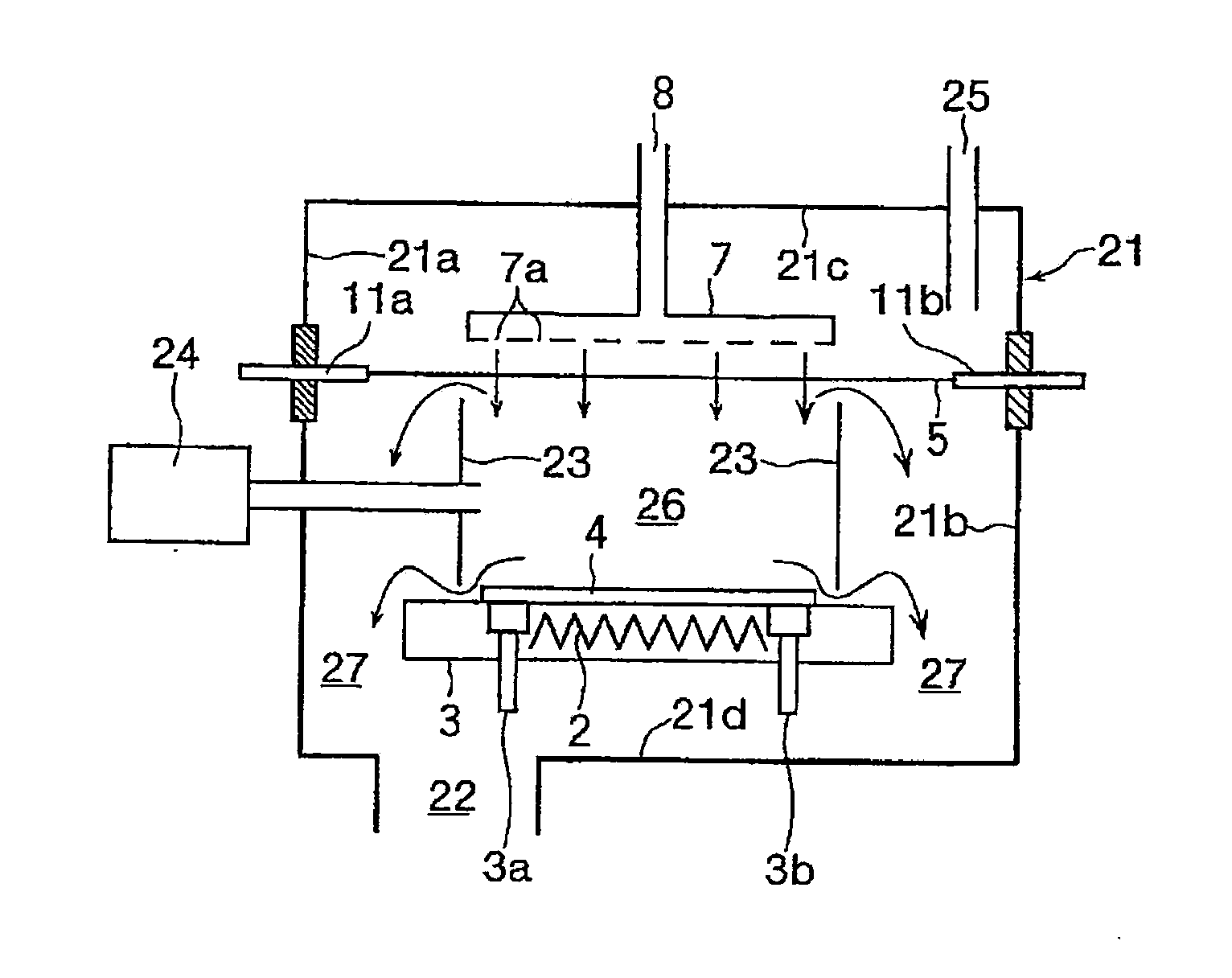
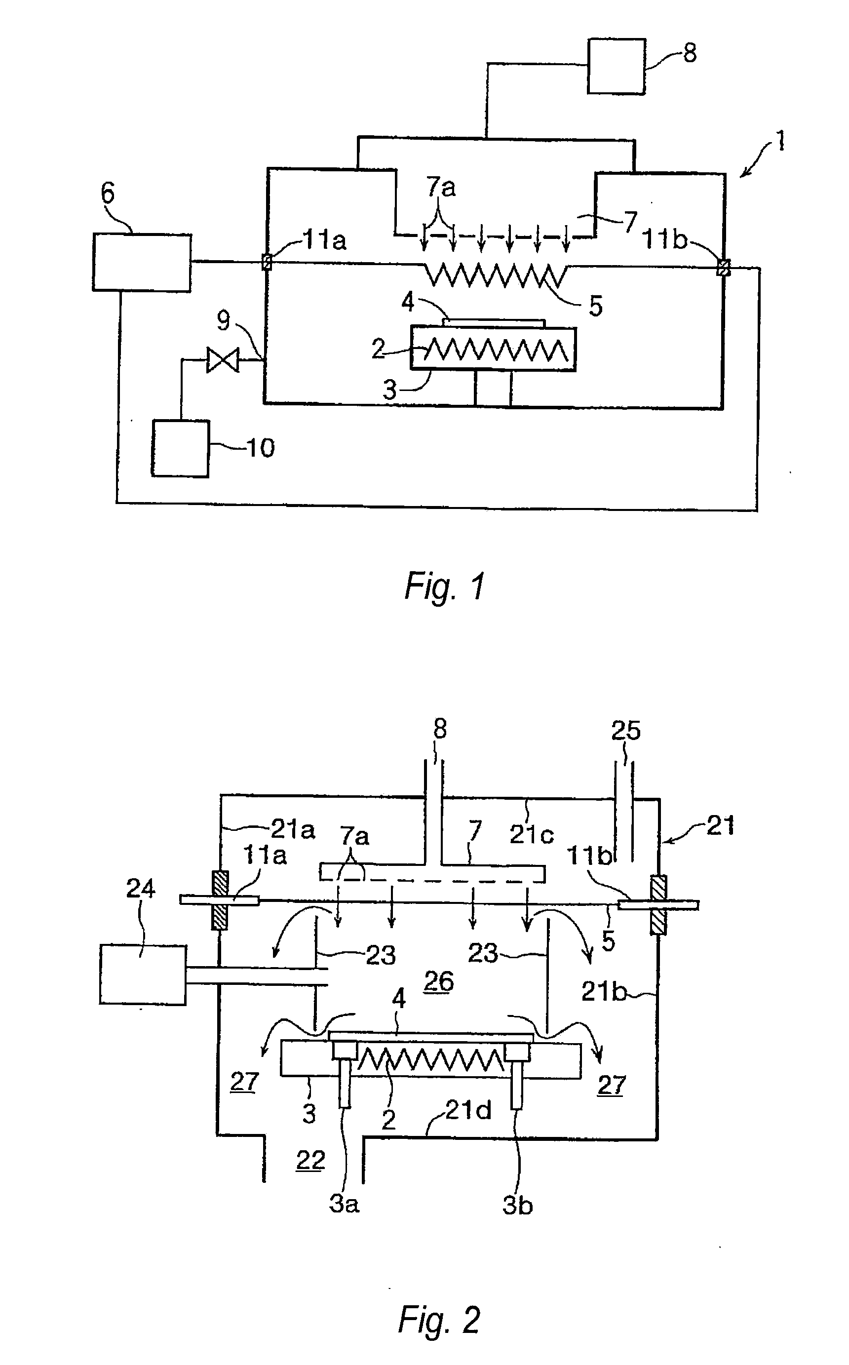
[0032]FIG. 2 is a schematic view depicting a first example of the catalytic chemical vapor deposition apparatus of the invention. Like the general catalytic chemical vapor deposition apparatus shown in FIG. 1, a substrate-placing platform 3 including a heater 2 therein, and a catalyst 5 comprising metal tungsten wire or metal iridium wire in the processing chamber 21, where the catalyst 5 is arranged in a manner such that the catalyst faces the substrate 4 on the placing platform 3. On the placing platform 3 are mounted ascent and descent pins 3a, 3b for receiving and transferring the substrate 4 during transfer. The catalyst 5 is supported and drawn with a tension with electric power input parts 11a, 11b arranged throughout the inner walls 21a, 21b facing each other.

[0033]On the inner wall 21c in the upper part of the processing chamber 21, a shower plate 7 equipped with a great number of gas nozzles 7a is arranged at a position directly above the catalyst 5, for jetting the raw ma...

example 2

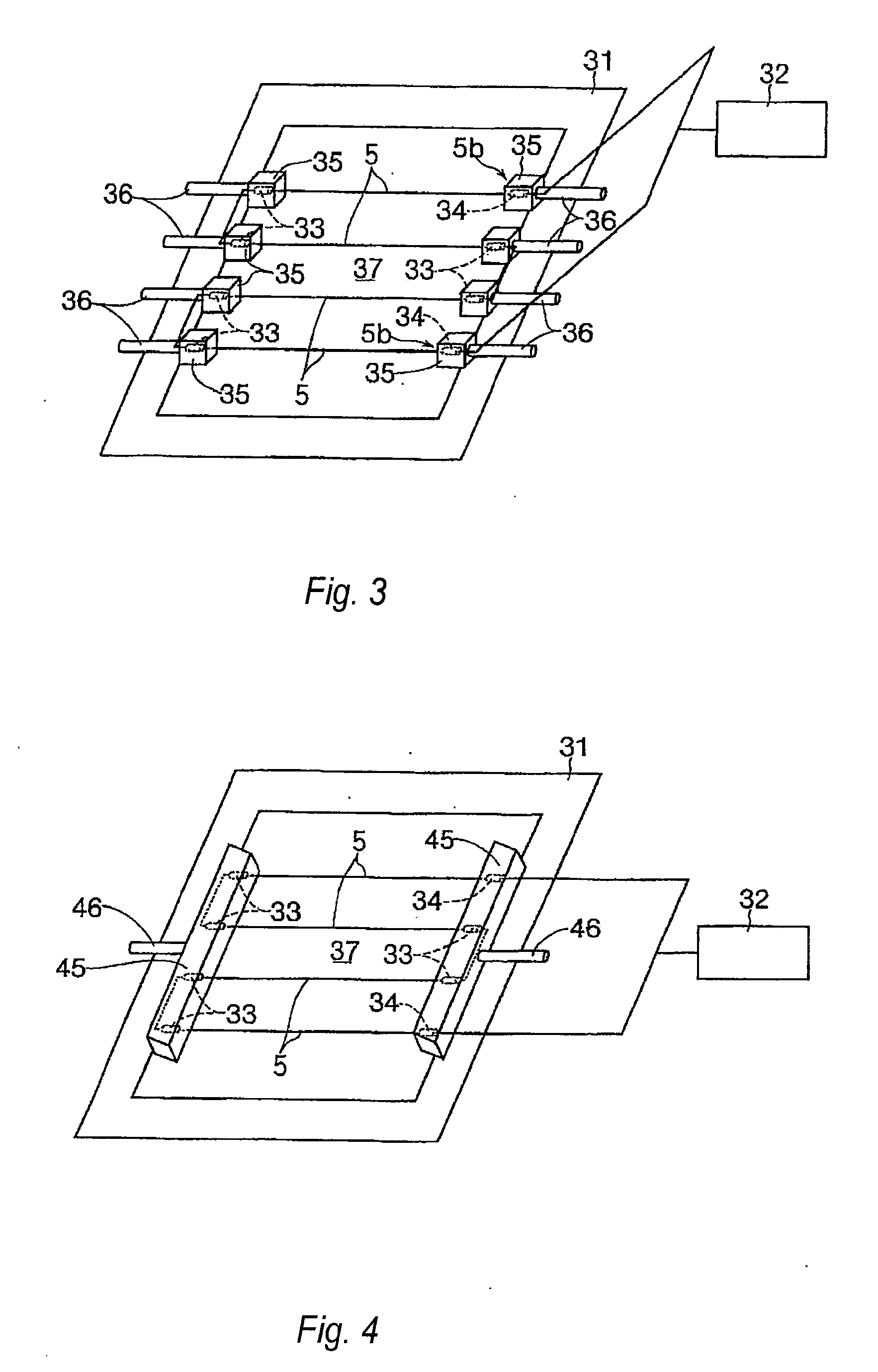
[0043]FIG. 3 is a schematic view of the essential part depicting a second example of the catalytic chemical vapor deposition apparatus of the invention, showing a catalyst wire-fixing frame 31 as an example for mounting the catalyst 5 and the electric power input parts 11a, 11b in the catalytic chemical vapor deposition apparatus shown in FIGS. 1 and 2.

[0044]In FIG. 3, the catalyst 5 is in direct connection with an outer electric power supply source 32. On the turn point thereof, the catalyst 5 is supported and fixed on the frame 31, with a support terminal 33. Both the ends 5b, 5b of the catalyst 5 are connected through connection terminals 34, 34 also working as support terminals for the frame 31 with the outer electric power supply source 32.

[0045]Then, the support terminal 33 and the connection terminal 34 as arranged on plural positions are individually covered with a hollow cover 35, while a gas discharge tube 36 in connection with an auxiliary gas discharge unit (not shown in...

example 3

[0048]FIG. 4 is a schematic view of the essential part depicting a third example of the catalytic chemical vapor deposition apparatus of the invention. In the catalyst wire-fixing frame 31 shown in FIG. 3, the hollow cover 35 is arranged for each of the support terminal 33 and the connection terminal 34. However, the hollow cover 45 in the third example is in an integral structure for placing collectively the support terminal 33 or connection terminal 34 arranged on the same side on the frame 31. Simultaneously, the gas discharge tube 46 for discharging gas from the inside of the hollow cover 45 may comprise a single gas discharge tube.

[0049]By employing such structure for coordinated use, the structure of the apparatus is made simpler, while the pressure control in the inside of the hollow cover 45 toward the film formation region 37 can be done more easily.


PUM

PropertyMeasurementUnit
Pressureaaaaaaaaaa

Abstract

A catalytic chemical vapor deposition apparatus is provided for producing a thin film of desired film quality, by making a particle countermeasure against the release gas such as H2O and deposit materials from or on members composing the structure of the inside of the processing chamber and the inner wall of the processing chamber.
A catalytic chemical vapor deposition apparatus comprising a substrate 4 arranged in a processing chamber 1, a shower plate 7 facing the substrate 4, and a catalyst 5 comprising metal tungsten wire activating a raw material gas from the shower plate 7, where the catalyst 5 is interposed between the substrate 4 and the shower plate 7 and where a cylindrical peripheral wall 23 encloses the space where the substrate 4 and the shower plate 7 face each other in the processing chamber 1, and additionally comprising a vacuum gas discharge unit so as to make the pressure inside the cylindrical peripheral wall 23, namely the pressure in the film formation region 26 higher than that in the other region.

Description

TECHNICAL FIELD[0001]The present invention relates to a catalytic chemical vapor deposition apparatus for depositing a thin film on a substrate, by decomposing a raw material gas utilizing the action of a catalyst generating heat via electricity.BACKGROUND OF THE INVENTION[0002]As the film deposition method for producing various semiconductor devices and liquid crystal displays, for example, the chemical vapor deposition process (CVD process) has been used widely.[0003]As the CVD process, for example, thermal CVD process and plasma CVD process have been known traditionally. In recent years, however, a catalytic chemical vapor deposition process (also referred to as catalytic CVD process, Cat-CVD process or hot wire CVD process) has been utilized practically, using a wire of for example tungsten heated via electricity (referred to as “catalyst” hereinafter) as the catalyst, where a raw material gas supplied into a reaction chamber is decomposed by the catalytic action of the catalyst...

Claims


Application Information

Patent Timeline
IPC IPC(8): C23C16/46
CPCC23C16/4401C23C16/45591C23C16/4488C23C16/54C23C16/4412H01L21/0262
Inventor TAKAGI, MAKIKOITOH, HIROMISAITO, KAZUYAFUJIMOTO, HIDEKI
Owner ULVAC INC
Why Eureka
Try Eureka