Electrode protection in both aqueous and non-aqueous electrochemical cells, including rechargeable lithium batteries

a technology of electrochemical cells and electrochemical cells, applied in secondary cells, cell components, sustainable manufacturing/processing, etc., can solve the problems of premature depletion of li and battery cycle life, interference with charge transport to the underlying, and impede the commercialization of lithium cells. , to achieve the effect of preventing electronic communication

Active Publication Date: 2009-11-26
SION POWER CORP
View PDF3 Cites 44 Cited by
  • Summary
  • Abstract
  • Description
  • Claims
  • Application Information

AI Technical Summary

Benefits of technology

[0014]Other advantages and novel features of the present invention will become apparent from the following detailed description of various non-limiting embodiments of the invention when considered in conjunction with the accompanying figures. In cases where the present specification and a document incorporated by reference include conflicting and / or inconsistent disclosure, the present specification shall control. If two or more documents incorporated by reference include conflicting and / or inconsistent disclosure with respect to each other, then the document having the later effective date shall control.
[0015]Non-limiting embodiments of the present invention will be described by way of example with reference to the accompanying figures, which are schematic and are not intended to be drawn to scale. In the figures, each identical or nearly identical component illustrated is typically represented by a single numeral. For purposes of clarity, not every component is labeled in every figure, nor is every component of each embodiment of the invention shown where illustration is not necessary to allow those of ordinary skill in the art to understand the invention. In the figures:
[0016]FIG. 1 shows a structure for use in an electrochemical cell, including a single-ion conductive layer and a polymer layer, according to one embodiment of the invention;
[0017]FIG. 2 shows a structure for use in an electrochemical cell, including several multi-layered structures, according to an embodiment of the invention;
[0018]FIG. 3 shows a structure for use in an electrochemical cell, including an embedded layer, according to an embodiment of the invention;
[0019]FIG. 4 shows a structure for use in an electrochemical cell, including an embedded layer comprising a multi-layered structure, according to an embodiment of the invention;
[0020]FIG. 5 shows SEM images of Li anode surfaces after a 10th discharge, according to an embodiment of the invention;
[0021]FIG. 6 shows a schematic diagram of an embodiment that increases the barrier to passage of a species;
[0022]FIG. 7 shows a structure for use in an electrochemical cell, including several multi-layered structures, embedded layers, and separation layers, according to an embodiment of the invention; and
[0023]FIG. 8 shows SEM images of Li anode surfaces after a 1st discharge, according to an embodiment of the invention.
[0024]The present invention relates to electrode protection in electrochemical cells, and more specifically, to electrode protection in both aqueous and non-aqueous electrochemical cells, including rechargeable lithium batteries. In most embodiments described herein, lithium rechargeable batteries (including lithium anodes) are described. However, wherever lithium batteries are described herein, it is to be understood that any analogous alkali metal battery (alkali metal anode) can be used. Additionally, although rechargeable batteries are primarily disclosed herein, non-rechargeable (primary) batteries are intended to benefit from the invention as well. Furthermore, although the invention is particularly useful in providing anode protection, such that high-cycle life aqueous rechargeable batteries (batteries using an aqueous-based electrolyte) are enabled, the invention is also applicable to non-aqueous-based electrolyte batteries.
[0025]The invention provides techniques and components for superior protection of and / or maintenance of electrodes (especially lithium anodes) in rechargeable and other batteries. Components of the invention provide, at least, one or more of the following features: (1) protection of an electrode from one or more components of an electrolyte that can react with or otherwise hasten the demise of (shorten the cycle life of) the electrode and / or overall device, (2) control over dissolution of anode material into electrolyte (e.g., reduction of lithium to lithium ion), and re-plating of electrode material from the electrolyte (e.g., oxidation of lithium ion to lithium metal), at the anode, and / or (3) superior control of desirable passage of components from the electrode to the electrolyte (e.g., lithium ion) while inhibiting passage of undesirable components from the electrolyte to the electrode that can damage the electrode.
[0026]In one embodiment, an electrochemical cell of the invention includes an anode comprising lithium, and a multi-layered structure positioned between the anode and an electrolyte of the cell. In one specific embodiment providing superior interaction between the multi-layered structure and the electrode, the multi-layered structure includes at least a first single-ion conductive material layer (e.g., a lithiated metal layer), and at least a first polymeric layer positioned between the anode and the single-ion conductive material. In this embodiment, the multi-layered structure can include several sets of alternating single-ion conductive material layers and polymeric layers. The multi-layered structures can allow passage of lithium ions, while limiting passage of certain chemical species that may adversely affect the anode (e.g., water). The cells may also include an separation layer (e.g., a plasma-treated layer) positioned between the anode and the multi-layered structure. This separation layer can act as a temporary or permanent protective layer, e.g., to cause uniform depletion and / or re-plating of lithium across the surface of the anode.
[0027]As noted in the embodiment thus far described, a lithium electrode, with or without a separation layer, is first directly addressed by a polymeric layer. On the side of the polymeric layer opposite that of the electrode, a single-ion conductive material layer is provided. Additional layers can be further provided. This arrangement can provide significant advantage, as polymers can be selected that impart flexibility to the system where it can be needed most, namely, at the surface of the electrode where morphological changes occur upon charge and discharge. In one specific embodiment, the polymer is particularly pliable and / or elastic (non-brittle) to provide a particularly durable, robust, rechargeable battery. In this arrangement the polymer can have at least one of the following properties, or a combination of any number of these properties: a Shore A hardness of less than 100, less than 80, less than 60, less than 40, or less than 20, (or a Shore A hardness between 0 and 10, between 10 and 20, between 20 and 30, between 30 and 40, between 40 and 50, between 50 and 60, between 60 and 70, between 70 and 80, between 80 and 90, or between 90 and 100), or a Shore D hardness of less than 100, less than 80, less than 60, less than 40, or less than 20 (or a Shore D hardness between 0 and 10, between 10 and 20, between 20 and 30, between 30 and 40, between 40 and 50, between 50 and 60, between 60 and 70, between 70 and 80, between 80 and 90, or between 90 and 100); a Young's Modulus (elastic modulus) of less than 10 GPa, less than 5 GPa, less than 3 GPa, less than 1 GPa, less than 0.1 GPa, or less than 0.01 GPa (or a Young's Modulus between 0.01 and 0.1 GPa, between 0.1 and 1 GPa, between 1 and 2.5 GPa, between 2.5 and 5 GPa); and an average fracture toughness of greater than 0.1 MN / m3 / 2, greater than 0.5 MN / m3 / 2, greater than 1.0 MN / m3 / 2, greater than 2.0 MN / m3 / 2, greater than 3.0 MN / m3 / 2, or greater than 5 MN / m3 / 2 (e.g., as measured at room temperature and atmospheric pressure). Appropriate polymers may also be chosen based on one or more properties relevant to use in an environment as described herein, such as: glass transition temperature (Tg), melting point (Tm), strength (e.g., compressional, tensile, flexural, and yield strength), elongation, plasticity, and hardness (e.g., as measured by a Shore A or Shore D durometer, or the Rockwell hardness test). This arrangement, comprising a depletable / re-platable electrode, polymer protective layer, and single-ion-conductive layer as a sub-combination of an overall protective structure or overall battery, adds significant advantage. In this and other arrangements, single-ion-conductive layers can be selected among those described herein and generally known in the art including glasses, lithiated metal layers, and the like.
[0028]Most single thin film materials, when deposited on the surface of a Li anode, do not have all of the necessary properties of passing Li ions, forcing a substantial amount of the Li surface to participate in current conduction, protecting the metallic Li anode against certain species (e.g., liquid electrolyte and / or polysulfides generated from a sulfur-based cathode) migrating from the cathode, and impeding high current density-induced surface damage. The present inventors have developed solutions to these problems through several embodiments of the invention, including the use of multi-layered anode stabilization layers (electrode stabilization), embedded Li layers (e.g., embodiments including a first Li layer, a Li conducting and electron insulating layer, and a second Li layer), and separation layers (e.g., plasma treated layers), as discussed in greater detail below.
[0029]FIG. 1 shows one example of an electrode protective arrangement of the invention, exemplified as a multi-layered anode stabilization layer structure. In the embodiment illustrated in FIG. 1, structure 10 includes anode 20 comprising a base electrode material (e.g., lithium), and multi-layered structure 22 covering the anode. In some cases herein, the anode is referred to as an “anode based material,”“anode active material,’ or the like, and the anode along with any protective structures are referred to collectively as the “anode.” All such descriptions are to be understood to form part of the invention. In this particular embodiment, multi-layered structure 22 includes single-ion conductive material 50, polymeric layer 40 positioned between the base electrode material and the single-ion-conductive material, and separation layer 30 (e.g., a layer resulting from plasma treatment of the electrode) positioned between the electrode and the polymeric layer. Multi-layered structures can allow passage of lithium ions and may impede the passage of other components that may otherwise damage the anode. Advantageously, multi-layered structures can reduce the number of defects and thereby force a substantial amount of the Li surface to participate in current conduction, impede high current density-induced surface damage, and / or act as an effective barrier to protect the anode from certain species (e.g., electrolyte and / or polysulfides), as discussed in greater detail below.
[0030]Anode 20 can comprise a base electrode material such as lithium metal, which can serve as the anode active material. The lithium metal may be in the form of, e.g., a lithium metal foil or a thin lithium film that has been deposited on a substrate, as described below. The lithium metal may also be in the form of a lithium alloy such as, for example, a lithium-tin alloy or a lithium aluminum alloy.
[0031]In this and other embodiments, the thickness of the anode may vary from, e.g., about 2 to 200 microns. For instance, the anode may have a thickness of less than 200 microns, less than 100 microns, less than 50 microns, less than 25 microns, less than 10 microns, or less than 5 microns. The choice of the thickness may depend on cell design parameters such as the excess amount of lithium desired, cycle life, and the thickness of the cathode electrode. In one embodiment, the thickness of the anode active layer is in the range of about 2 to 100 microns. In another embodiment, the thickness of the anode is in the range of about 5 to 50 microns. In another embodiment, the thickness of the anode is in the range of about 5 to 25 microns. In yet another embodiment, the thickness of the anode is in the range of about 10 to 25 microns.
[0032]The device illustrated in FIG. 1. may further comprise a substrate, as is known in the art, on the surface of the anode opposite that of the multi-layer structure. Substrates are useful as a support on which to deposit the anode active material, and may provide additional stability for handling of thin lithium film anodes during cell fabrication. Further, in the case of conductive substrates, a substrate may also function as a current collector useful in efficiently collecting the electrical current generated throughout the anode and in providing an efficient surface for attachment of electrical contacts leading to an external circuit. A wide range of substrates are known in the art of anodes. Suitable substrates include, but are not limited to, those selected from the group consisting of metal foils, polymer films, metallized polymer films, electrically conductive polymer films, polymer films having an electrically conductive coating, electrically conductive polymer films having an electrically conductive metal coating, and polymer films having conductive particles dispersed therein. In one embodiment, the substrate is a metallized polymer film. In other embodiments, described more fully below, the substrate may be selected from non-electrically-conductive materials.
[0033]The layers of the anode structure 10 of the present invention may be deposited by any of a variety of methods generally known in the art, such as physical or chemical vapor deposition methods, extrusion, and electroplating. Examples of suitable physical or chemical vapor deposition methods include, but are not limited to, thermal evaporation (including, but not limited to, resistive, inductive, radiation, and electron beam heating), sputtering (including, but not limited to, diode, DC magnetron, RF, RF magnetron, pulsed, dual magnetron, AC, MF, and reactive), chemical vapor deposition, plasma enhanced chemical vapor deposition, laser enhanced chemical vapor deposition, ion plating, cathodic arc, jet vapor deposition, and laser ablation.
[0034]Deposition of the layers may be carried out in a vacuum or inert atmosphere to minimize side reactions in the deposited layers which could introduce impurities into the layers or which may affect the desired morphology of the layers. In some embodiments, anode active layers and the layers of multi-layered structures are deposited in a continuous fashion in a multistage deposition apparatus.
[0035]Specifically, methods for depositing anode 20 (e.g., in the case of an alkali metal anode such as lithium) onto a substrate include methods such as thermal evaporation, sputtering, jet vapor deposition, and laser ablation. Alternatively, where the anode comprises a lithium foil, or a lithium foil and a substrate, these can be laminated together by a lamination process as known in the art, to form an anode layer.
[0036]In some embodiments, the single-ion conductive material is non-polymeric. E.g., in certain embodiments, the single-ion conductive material 50 is defined in part or in whole by a metal layer that is highly conductive toward lithium and minimally conductive toward electrons. In other words, the single-ion conductive material may be one selected to allow lithium ions, but to impede electrons, from passing across the layer. The metal layer may comprise a metal alloy layer, e.g., a lithiated metal layer especially in the case where a lithium anode is employed. The lithium content of the metal alloy layer may vary from about 0.5% by weight to about 20% by weight, depending, for example, on the specific choice of metal, the desired lithium ion conductivity, and the desired flexibility of the metal alloy layer. Suitable metals for use in the single-ion conductive material include, but are not limited to, Al, Zn, Mg, Ag, Pb, Cd, Bi, Ga, In, Ge, Sb, As, and Sn. Sometimes, a combination of metals, such as the ones listed above, may be used in a single-ion conductive material.
[0037]In other embodiments, the single-ion conductive material may include a ceramic layer, for example, a single ion conducting glass conductive to lithium ions. Suitable glasses include, but are not limited to, those that may be characterized as containing a “modifier” portion and a “network” portion, as known in the art. The modifier may include a metal oxide of the metal ion conductive in the glass. The network portion may include a metal chalcogenide such as, for example, a metal oxide or sulfide. Single-ion conductive layers may include glassy layers comprising a glassy material selected from the group consisting of lithium nitrides, lithium silicates, lithium borates, lithium aluminates, lithium phosphates, lithium phosphorus oxynitrides, lithium silicosulfides, lithium germanosulfides, lithium oxides (e.g., Li2O, LiO, LiO2, LiRO2, where R is a rare earth metal), lithium lanthanum oxides, lithium titanium oxides, lithium borosulfides, lithium aluminosulfides, and lithium phosphosulfides, and combinations thereof. In one embodiment, the single-ion conductive layer comprises a lithium phosphorus oxynitride in the form of an electrolyte. Electrolyte films of lithium phosphorus oxynitride suitable for use as the single ion conductive material 50 are disclosed, for example, in U.S. Pat. No. 5,569,520 to Bates. The selection of the single ion conducting material will be dependent on a number of factors including, but not limited to, the properties of electrolyte and cathode used in the cell.
[0038]For cells used in a water and / or air environment, such as a rechargeable battery with an aqueous-based electrolyte, the single-ion conductive material may be constructed so as to impede the passage of hydrogen ions (protons) across its layer. For instance, during discharge protons may move against the electric field in a protective layer (e.g., a multi-layered structure) of a cell. However, during charge, the electric field may accelerate the penetration of protons across the protective layer. Eventually protons may reach a Li anode layer and generate, e.g., hydrogen gas or other species, which may form bubbles and can cause delamination, or other undesirable effects, in a multi-layered structure. As discussed in more detail below, the single-ion conductive layer may be combined with other materials (e.g., impregnated with a polymer) to impede the passage of hydrogen ions and / or or electrons, while permitting the passage of lithium ions.
[0039]The thickness of a single-ion conductive material layer (e.g., within a multi-layered structure) may vary over a range from about 1 nm to about 10 microns. For instance, the thickness of the single-ion conductive material layer may be between 1-10 nm thick, between 10-100 nm thick, between 100-1000 nm thick, between 1-5 microns thick, or between 5-10 microns thick. The thickness of a single-ion conductive material layer may be no greater than, e.g., 10 microns thick, no greater than 5 microns thick, no greater than 1000 nm thick, no greater than 500 nm thick, no greater than 250 nm thick, no greater than 100 nm thick, no greater than 50 nm thick, no greater than 25 nm thick, or no greater than 10 nm thick. In some cases, the single-ion conductive layer has the same thickness as a polymer layer in a multi-layered structure.
[0040]The single-ion conductive layer may be deposited by any suitable method such as sputtering, electron beam evaporation, vacuum thermal evaporation, laser ablation, chemical vapor deposition (CVD), thermal evaporation, plasma enhanced chemical vacuum deposition (PECVD), laser enhanced chemical vapor deposition, and jet vapor deposition. The technique used may depend on the type of material being deposited, the thickness of the layer, etc.
[0041]In some embodiments, single-ion conducting layers can be treated with a polymer such that pinholes and / or nanopores of the single-ion conducting layers may be filled with the polymer. Such embodiments can impede the diffusion of certain species (e.g., electrolyte and / or polysulfides) towards the anode, e.g., by increasing the distance, and tortuosity, through which such a species would need to pass to penetrate the entire multi-layer arrangement to arrive at the anode, as discussed in greater detail below.
[0042]The thickness of a polymer layer (e.g., within a multi-layered structure) may vary over a range from about 0.1 microns to about 10 microns. For instance, the thickness of the polymer layer may be between 0.1-1 microns thick, between 1-5 microns thick, or between 5-10 microns thick. The thickness of a polymer layer may be no greater than, e.g., 10 microns thick, no greater than 5 microns thick, no greater than 2.5 microns thick, no greater than 1 micron thick, no greater than 0.5 microns thick, or no greater than 0.1 microns thick.
[0043]In some embodiments including a multi-layered structure having more than one polymer layer, the thicknesses of the polymer layers can vary within the structure. For instance, in some cases, the polymer layer closest to the anode layer (e.g., a Li reservoir) is thicker than the other polymer layers of the structure. This embodiment can, for example, stabilize the anode by allowing lithium ions to plate out more uniformly across the surface of the anode during charge.
[0044]A polymer layer may be deposited by method such as electron beam evaporation, vacuum thermal evaporation, laser ablation, chemical vapor deposition, thermal evaporation, plasma assisted chemical vacuum deposition, laser enhanced chemical vapor deposition, jet vapor deposition, and extrusion. The polymer layer may also be deposited by spin-coating techniques. A method for depositing crosslinked polymer layers includes flash evaporation methods, for example, as described in U.S. Pat. No. 4,954,371 to Yializis. A method for depositing crosslinked polymer layers comprising lithium salts may include flash evaporation methods, for example, as described in U.S. Pat. No. 5,681,615 to Afftnito et al. The technique used for depositing polymer layers may depend on the type of material being deposited, the thickness of the layer, etc.
[0045]As noted in the description with respect to FIG. 1 thus far, in one particular embodiment, the protective structure separating anode 20 from electrolyte 60 includes a polymer layer adjacent the anode (or separation layer) 30. In other arrangements, a polymer layer need not be the first layer adjacent the anode or separation layer. Various arrangements of the invention, including various multi-layered structures, are described below in which the first layer adjacent the anode may or may not be polymeric. It is to be understood that in all arrangements where any particular arrangement of layers is shown, alternate ordering of layers is within the scope of the invention. Notwithstanding this, one aspect of the invention includes the particular advantages realized by a non-brittle polymer immediately adjacent the anode or separation layer.
[0046]In some embodiments, multi-layered structures protect the anode better than any individual layer that is included in the structure. For instance, each of the layers of a multi-layered structure, e.g., the single-ion conducting layers, the polymer layers, or the separation layer, may possess desirable properties, but at the same time may be most effective when complemented by other components with different properties. For example, single-ion conducting layers, especially vacuum deposited single-ion conducting layers, may be flexible as thin films, but when deposited as thicker layers, may include defects such as pinholes and / or roughness, and may crack when handled. Polymer layers, and especially crosslinked polymer layers, for example, can provide very smooth surfaces, may add strength and flexibility, and may be electron insulating, but may pass certain solvents and / or liquid electrolytes. Accordingly, these are examples of layers that can complement each other in an overall improved protective structure.
[0047]Accordingly, in another embodiment, the invention provides a multi-layered electrode stabilization or protection structure that provides many advantages over existing electrode protective structures. In much of the description herein, the structure is referred to as an “anode stabilization” structure, but it is to be understood that the structure can be used for any electrode under suitable conditions as would be understood by those of ordinary skill in the art when taking into consideration the function of a particular electrode. Multi-layered electrode stabilization structures of the invention, according to this embodiment, are designed to minimize defects that might otherwise exist inherently in prior electrode protective structures, or that might exist inherently in electrode protective structures using the same or similar materials as those used in protective structures of the current invention, but arranged differently. For example, single ion-conductive layers (or other components of a device as described herein) may include pinholes, cracks and / or grain boundary defects. Once these defects are formed, they can grow / propagate through the entire thickness of the film as the film grows and may become worse as the film grows thicker. By separating thin single ion-conductive layers from each other with thin, pinhole free, smooth polymer layers, the defect structure in each single ion-conductive layer can be decoupled from the defect structure in every other single ion-conductive layer by an intervening polymer layer. Thus, at least one or more of the following advantages are realized in such a structure: (1) it is less likely for defects in one layer to be directly aligned with defects in another layer, and typically any defect in one layer is substantially non-aligned with a similar defect in another layer; (2) any defects in one single ion-conductive layer typically are much smaller and / or less detrimental than they would otherwise be in a thicker layer of otherwise similar or identical material. Where alternating single-ion conductive layers and polymer layers are deposited atop each other in a fabrication process, each single-ion conductive layer has a smooth, pinhole free, polymer surface upon which to grow. In contrast, where the single-ion conductive layer to be deposited atop another single-ion conductive layer (or continuously deposited as a single, thicker layer), defects in an underlying layer can serve to instigate defects in growth in a layer deposited atop an underlying layer. That is, whether a protective structure is built with thicker single-ion conductive layers or multiple single-ion conductive layers atop each other, defects can propagate through the thickness, or from layer to layer, as the structure grows, resulting in larger defects, and defects that propagate directly or substantially directly throughout the entire structure. In this arrangement, the single ion-conductive layers can also grow with fewer defects than would occur if they were deposited directly onto the rougher Li or electrolyte layers, particularly where the arrangement of FIG. 1 is employed in which the first electrode stabilization layer addressing the electrode is the polymer layer. Accordingly, in this arrangement, ion-conductive layers can be made that have overall fewer defects, defects that are not aligned with defects in nearest other ion-conductive layers and, where defects exist, they are typically significantly less detrimental (e.g., smaller) than would otherwise exist in a continuously-grown, thicker structure or layers of the same or similar material deposited on top of each other.
[0048]A multi-layered electrode stabilization structure can act as a superior permeation barrier by decreasing the direct flow of species (e.g., electrolyte and polysulfide species) to the Li anode, since these species have a tendency to diffuse through defects or open spaces in the layers. Consequently, dendrite formation, self discharge, and loss of cycle life can be reduced.
[0049]Another advantage of a multi-layered structure includes the mechanical properties of the structure. The positioning of a polymer layer adjacent a single-ion conductive layer can decrease the tendency of the single-ion conductive layer to crack, and can increase the barrier properties of the structure. Thus, these laminates may be more robust towards stress due to handling during the manufacturing process than structures without intervening polymer layers. In addition, a multi-layered structure can also have an increased tolerance of the volumetric changes that accompany the migration of lithium back and forth from the anode during the cycles of discharge and charge of the cell.
[0050]The ability of certain species that can be damaging to the anode (e.g., electrolytes and / or polysulfides) to reach the anode can also be decreased by providing repeated layers of single-ion conductive layers and polymer layers in a multi-layered structure. When a species encounters a defect-free portion of a single-ion conductive layer, transport of the species towards the anode is possible if the species diffuses laterally through a very thin polymer layer to encounter a defect in a second single-ion conductive layer. Since lateral diffusion through ultra-thin layers is very slow, as the number of single-ion conductive / polymer layer pairs increases, the rate of diffusion of species becomes extremely small (e.g., the amount of penetration across the layer decreases). For instance, in one embodiment, permeation of a species through polymer / single-ion conductive / polymer 3-layer structures can be reduced by three orders of magnitude over a single single-ion conductive layer alone (e.g., even though layers alone may have poor barrier properties). In another embodiment, a polymer / single-ion conductive / polymer / single-ion conductive / polymer 5-layer structure may have more than five orders of magnitude reduction of permeation of a species compared to that in a single single-ion conductive layer. By contrast, permeation of the same species through a double-thick single-ion conductive layer may actually increase. These significant reductions in permeation of destructive species through the electrode stabilization layer can increase as the number of layers increases where the thickness of individual layers decreases. That is, in comparison to a two-layer structure of a single-ion conductive layer and polymer layer of a particular, overall thickness, a ten-layer structure of alternating single-ion conductive layers and polymer layers of the same overall thickness can vary significantly decreased permeation of unwanted species through the layer. Specific arrangements are described below, and a principal involved in the increased barrier to passage of these species is schematically illustrated below in FIG. 6. Because of the significant advantage realized by electrode stabilization protection of the invention, overall lower amounts of material can be used in a particular protective structure, as compared to prior art structures. Accordingly, at a particular level of electrode protection needed in a particular battery arrangement, a significantly smaller mass of overall electrode stabilization materials can be employed, significantly reducing overall battery weight.
[0051]A multi-layered structure can include various numbers of polymer / single-ion conductive pairs as needed. Generally, a multi-layered structure can have n polymer / single-ion conductive pairs, where n can be determined based on a particular performance criteria for a cell. E.g., n can be an integer equal to or greater than 1, or equal to or greater than 2, 3, 4, 5, 6, 7, 10, 15, 20, 40, 60, 100, or 1000, etc. In some embodiments, a multi-layered structure can include greater than 4, greater than 10, greater than 25, greater than 50, greater than 100, greater than 200, greater than 500, greater than 1000, greater than 2000, greater than 3000, greater than 5000, or greater than 8000 polymer / single-ion conductive pairs. For example, in one particular embodiment, greater than 10,000 polymer / single-ion conductive pairs were fabricated.

Problems solved by technology

Unfortunately, the reactivity of lithium and the associated cycle life, dendrite formation, electrolyte compatibility, fabrication and safety problems have hindered the commercialization of lithium cells.
This process is stressful to the anode in many ways, and can lead to premature depletion of Li and reduction of the battery cycle life.
Many of the inactive reaction products associated with overall Li loss from the anode upon cycling can also accumulate on the increasingly roughened Li surface and may interfere with charge transport to the underlying metallic Li anode.
In the absence of other degradation processes in other parts of the battery, the per-cycle Li anode loss alone can eventually render the cell inactive.
Especially at higher current density (which is commercially desirable) these processes can lead to quicker cell death.
For example, reaction of a lithium anode with the electrolyte may result in the formation of resistive film barriers on the anode, which can increase the internal resistance of the battery and lower the amount of current capable of being supplied by the battery at the rated voltage.
While a variety of techniques and components for protection of lithium and other alkali metal anodes are known, especially in rechargeable batteries, these protective coatings present particular challenges.
Rechargeable (secondary) lithium batteries present a particular challenge in connection with their use with aqueous electrolytes.

Method used


Image

  • Electrode protection in both aqueous and non-aqueous electrochemical cells, including rechargeable lithium batteries
  • Electrode protection in both aqueous and non-aqueous electrochemical cells, including rechargeable lithium batteries
  • Electrode protection in both aqueous and non-aqueous electrochemical cells, including rechargeable lithium batteries

Examples


example 1

Fabrication and Characterization of Lamanode Structures

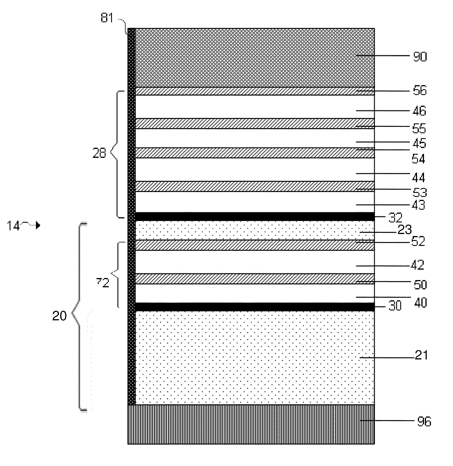
[0124]Lamanode structures, e.g., structures including a first and second layers of Li separated by an embedded layer that is conductive to Li ions, but substantially non-conductive to electrons, were fabricated by thermal evaporation (vacuum deposition) of Li on a PET substrate in two layers of Li with different thickness. The two layers of Li were separated by an embedded layer of a low-conductive material, e.g., LiPON, Li3N or etc. The ratio of the thickness of top and bottom Li layers was calculated based on a required DoD (depth of discharge) of the first discharge and was in the range between 0.2 to 0.4. A layer of about 0.01 to 1 micron LiPON was deposited on top of the bottom thicker Li layer by rf magnetron spattering from a Li3PO4 target in an N2 atmosphere. A thinner Li layer, e.g., 5 microns, was thermally evaporated on top of the embedded layer.

[0125]The top (thinner) Li layer interfacing the electrolyte was dissolve...

example 2

Cycle Lives of Lamanode Structures

[0130]This example shows that the Li cycling efficiency increases and the cycle life is longer for cells including laminode structures compared to cells having single layers of base electrode materials.

[0131]To fabricate control cells, prismatic cells with thermal evaporated Li on one side of 23 micron thickness of PET, Separator Tonen and a cathode containing 65% S coated on one side of a Rexam Al foil were sealed in a bag of Sealright. A mixture of ethers and Li imide salt was used as an electrolyte. The working surface of the anode was 400 cm2. The cells were tasted for cycle life performance at a discharge current of 200 mA to a cut-off of 1.8 V, and charge current of 0.1 A for 4 hours. Cycling results obtained from three control cells were obtained.

[0132]The same cell design as described above was built but with a first laminode anode structure (or “sandwich anode”) instead of a single-layered anode. The first laminode structure included a 20 m...

example 3

Effects of Different Types of Anode Protection on Discharge Capacity

[0137]This example shows effects of different types of anode protection on discharge capacity of a cell.

[0138]The control used in these experiments included a VDLi / CO2 structure, equivalent to a Li foil. A first test structure included a VDLi / CO2 / polymer (1500-2500 Angstroms) structure. A second test structure included a VDLi / CO2 / polymer (1500-2500 Angstroms) structure. A third test structure included a laminode (Sandwich anode) of VDLi / LiPON / VDLi / CO2 / SPE. In this particular experiment, each of the cells were cycled several times, and an improvement of 30-40% in cycle life was obtained when the cell included a polymer layer compared to a cell without a polymer layer. A significant improvement in cycle life was obtained when a cell included an embedded layer of LiPON compared to a cell without an embedded layer. A cell that included a laminode structure having an embedded layer and a polymer layer, e.g., a VDLi / LiPON...


PUM

PropertyMeasurementUnit
thicknessaaaaaaaaaa
thicknessaaaaaaaaaa
thicknessaaaaaaaaaa

Abstract

Electrode protection in electrochemical cells, and more specifically, electrode protection in both aqueous and non-aqueous electrochemical cells, including rechargeable lithium batteries, are presented. In one embodiment, an electrochemical cell includes an anode comprising lithium and a multi-layered structure positioned between the anode and an electrolyte of the cell. A multi-layered structure can include at least a first single-ion conductive material layer (e.g., a lithiated metal layer), and at least a first polymeric layer positioned between the anode and the single-ion conductive material. The invention also can provide an electrode stabilization layer positioned within the electrode, i.e., between one portion and another portion of an electrode, to control depletion and re-plating of electrode material upon charge and discharge of a battery. Advantageously, electrochemical cells comprising combinations of structures described herein are not only compatible with environments that are typically unsuitable for lithium, but the cells may be also capable of displaying long cycle life, high lithium cycling efficiency, and high energy density.

Description

RELATED APPLICATIONS[0001]This application is a divisional application of U.S. patent application Ser. No. 11 / 400,025, entitled “Electrode Protection in both Aqueous and Non-Aqueous Electrochemical Cells, Including Rechargeable Lithium Batteries”, filed Apr. 6, 2006 which claims priority under 35 U.S.C. § 119(e) to U.S. Provisional Application Ser. No. 60 / 785,768, entitled, “Lithium / Water, Lithium / Air Batteries,” filed on Mar. 22, 2006, both of which are incorporated herein by reference in their entireties.FIELD OF INVENTION[0002]The present invention relates to electrode protection in electrochemical cells, and more specifically, to electrode protection in both aqueous and non-aqueous electrochemical cells including rechargeable lithium batteries.BACKGROUND[0003]There has been considerable interest in recent years in developing high energy density batteries with lithium containing anodes. Lithium metal is particularly attractive as the anode of electrochemical cells because of its ...

Claims


Application Information

Patent Timeline
Patent Type & Authority Applications(United States)
IPC IPC(8): H01M10/44H01M4/02H01M4/13
CPCH01M4/02Y02E60/122H01M4/366H01M4/385H01M4/66H01M4/661H01M10/36H01M10/4235H01M2004/021H01M2004/027H01M2300/0002H01M4/628H01M2/1673H01M10/44H01M4/13Y02E60/10Y02P70/50H01M50/46H01M4/382H01M4/62
Inventor AFFINITO, JOHN D.MIKHAYLIK, YURIY V.GERONOV, YORDAN M.SHEEHAN, CHRISTOPHER J.
Owner SION POWER CORP
Why Eureka
Try Eureka