

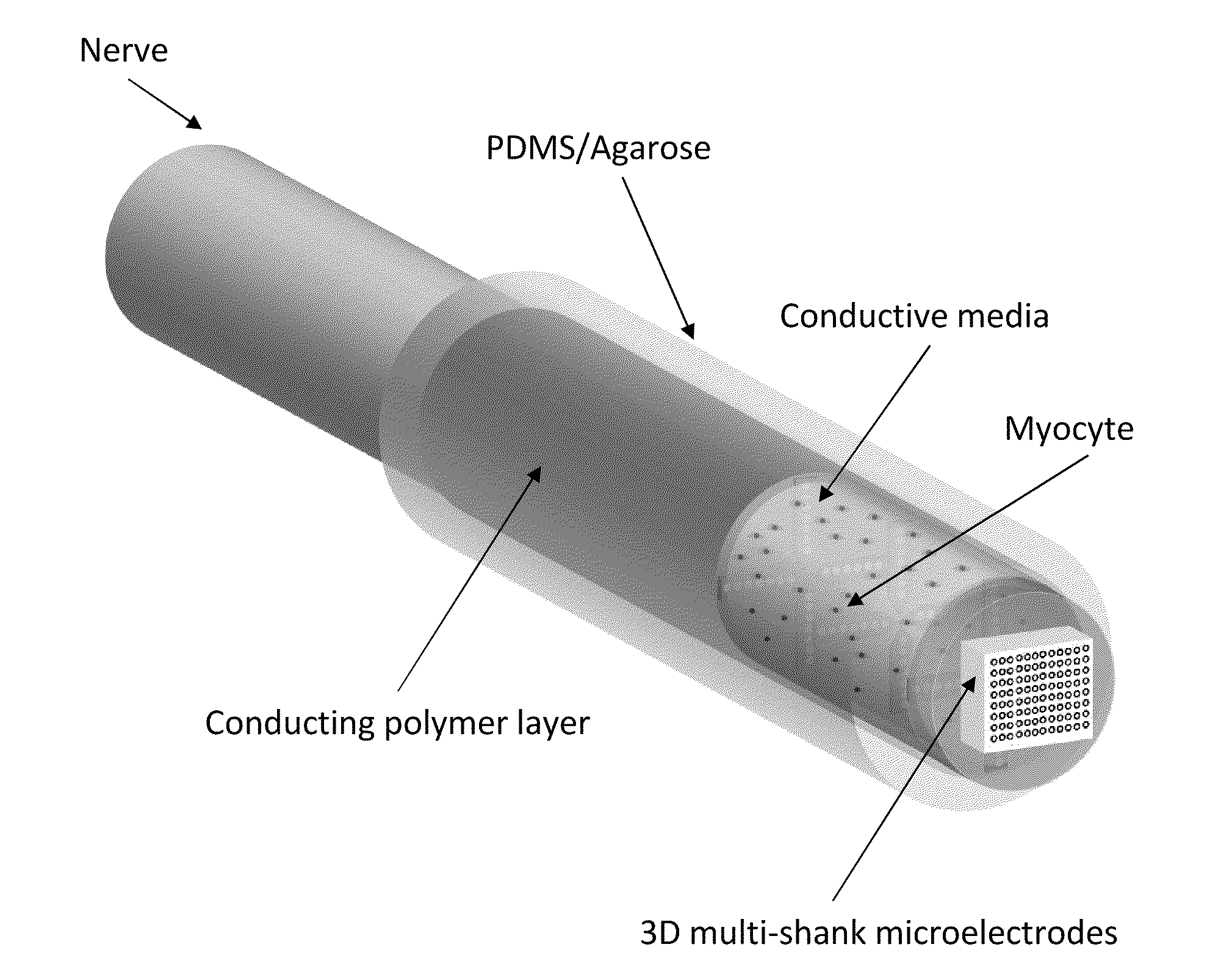
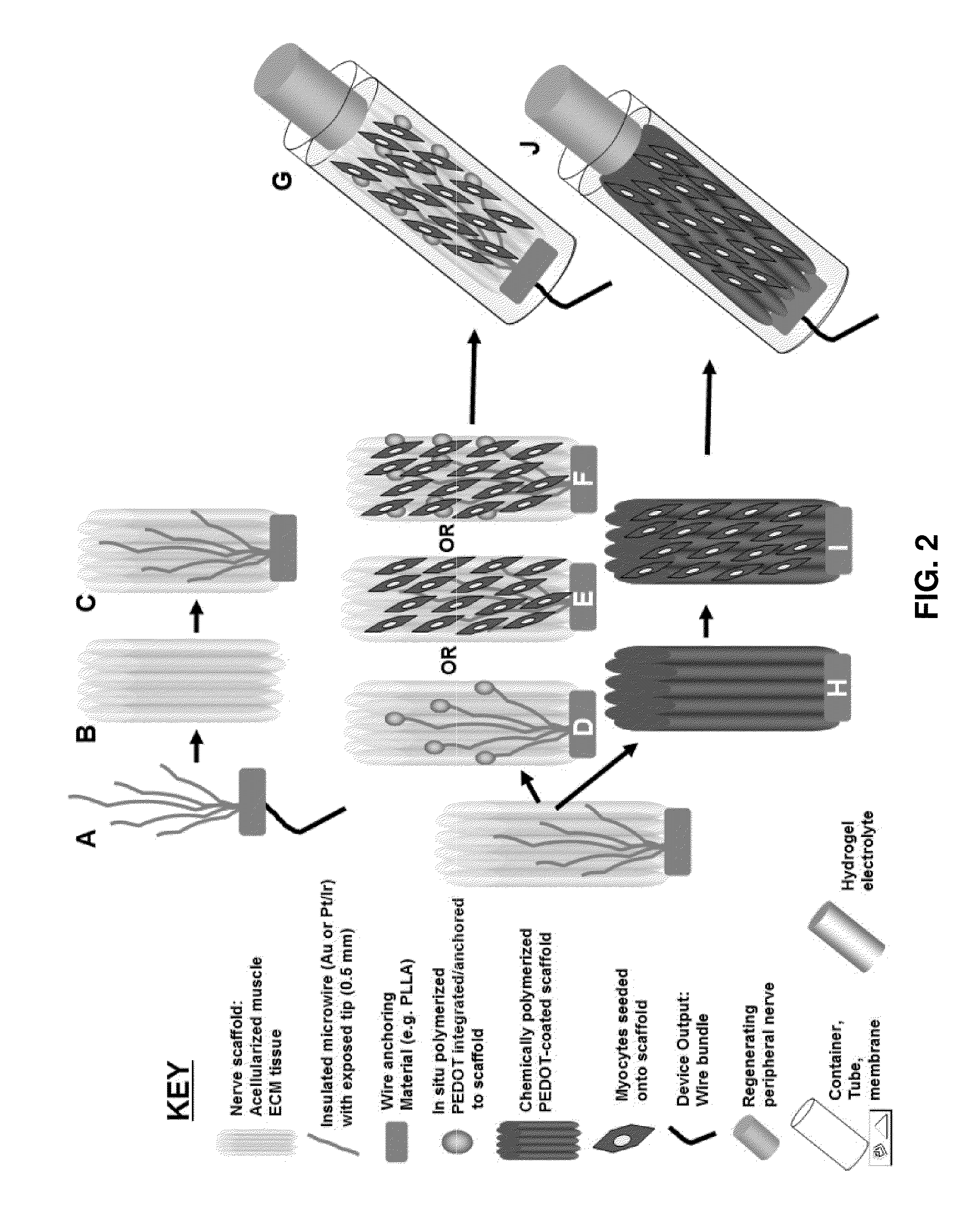
Hybrid bioelectrical interface device
a bioelectrical interface and hybrid technology, applied in the field of hybrid bioelectrical interface devices, can solve the problems of time-related signal degradation, preventing the achievement of individual axonal fidelity, and difficult interfacing mechanical with biological
- Summary
- Abstract
- Description
- Claims
- Application Information
AI Technical Summary
Benefits of technology
Problems solved by technology
Method used
Image


Examples
example 1
In Vivo Use of an Hybrid Bioelectrical Interface Device
[0070]Methods and Materials
[0071]Animal Model: Experiments were performed using two month old, male, specific pathogen free F344 rats (Charles River Laboratory, Kingston, N.Y.). Biosynthetic Construct Preparation: ACM neural interface constructs were prepared from acellularization of whole F344 rat lower limb (Charles River, Wilmington, Mass.) vastus lateralis muscles. The acellular muscles were then dissected into bundles of several myofibrils under microscopic magnification using a Nikon SMZ-10A stereomicroscope (Nikon Instruments, Melville, N.Y., USA). These bundles had a maximum fiber length of 20 mm and a diameter of 2.0-3.0 mm (approximate dimensions of an intact rat peroneal nerve). These fibers subsequently underwent a single-cycle chemical PEDOT polymerization process using iron chloride (III) (Eq. 1).
[0072]Experimental Groups: Electrophysiologic data was obtained in multiple experimental and control groups. Efferent pe...
PUM
| Property | Measurement | Unit |
|---|---|---|
| Permeability | aaaaa | aaaaa |
| Charge transfer state | aaaaa | aaaaa |
Abstract
Description
Claims
Application Information