
Raised bed planter with biomimetic exoskeleton

Inactive Publication Date: 2009-12-03
FOUNTAINHEAD
View PDF14 Cites 40 Cited by
  • Summary
  • Abstract
  • Description
  • Claims
  • Application Information

AI Technical Summary

Benefits of technology

[0029]In a preferred embodiment, the exoskeleton further comprises sand or grit to deter chewing damage from rodents. In an alternate embodiment, the raised bed planter further comprises an exterior layer of indoor / outdoor carpeting to add protection against wind desiccation while providing a cosmetic benefit.
[0035]In a preferred embodiment, the hydrophilic bedding fill material is lightweight, durable, hydrophilic and nontoxic to plant roots. Preferably, the hydrophilic bedding fill material comprises peat, ground bark, rockwool, perlite, coir, jute, cellulose sponge, pumice, silica and / or cotton. In an alternate embodiment, a non-hydrophilic filler is added to the bedding material to reduce cost and / or weight.
[0039]In a preferred embodiment, the raised bed planter further comprising a hydrophilic insert, capillary wicking channels and fiber wool fill; each wicking channel has a top portion; and the wicking channels transport water vertically upward from the hydrophilic insert to plants that are growing near the top portion of the wicking channels and that grow through holes cut through the exoskeleton. Preferably, the hydrophilic insert and wicking channels are comprised of materials that are lightweight, durable, hydrophilic, and nontoxic to plant roots.
[0044]In a preferred embodiment, the exoskeleton further comprises a strengthening material, and the strengthening material is selected from the group consisting of shotcrete, polyurethane foam, polyurethane, polyurea, construction adhesive, silicone and plastic wood filler. In an alternate embodiment, the raised bed planter has an overall weight, and the planter further comprises internal baffles to reduce the overall weight of the planter. Preferably, the internal baffles are comprised of polystyrene, polyurea-coated nonwoven polymer matting, or polyurethane foam.
[0047]In a preferred embodiment, portions of the exoskeleton are covered with outdoor carpeting to reduce moisture losses and / or for decorative purposes. In another preferred embodiment, each raised bed planter forms an interlocking planter unit that is joined to another interlocking planter unit by means of a tongue that fits into a groove in an adjoining interlocking planter; and the interlocking planter units are attached to a wall, fence or roof with a mounting plate that is attached to the interlocking planter units.

Problems solved by technology

Traditional planters are limited in that their designs are usually fairly rigid (for example, they do not allow for freeform shapes, nor do they allow for large and / or interlocking shapes), the structures of the planters may not be portable or durable, and they do not adequately deal with drainage of excess moisture.
Furthermore, the interior fill of most prior art planters does not provide for moisture retention and wicking.

Method used


Image

  • Raised bed planter with biomimetic exoskeleton
  • Raised bed planter with biomimetic exoskeleton
  • Raised bed planter with biomimetic exoskeleton

Examples


first embodiment

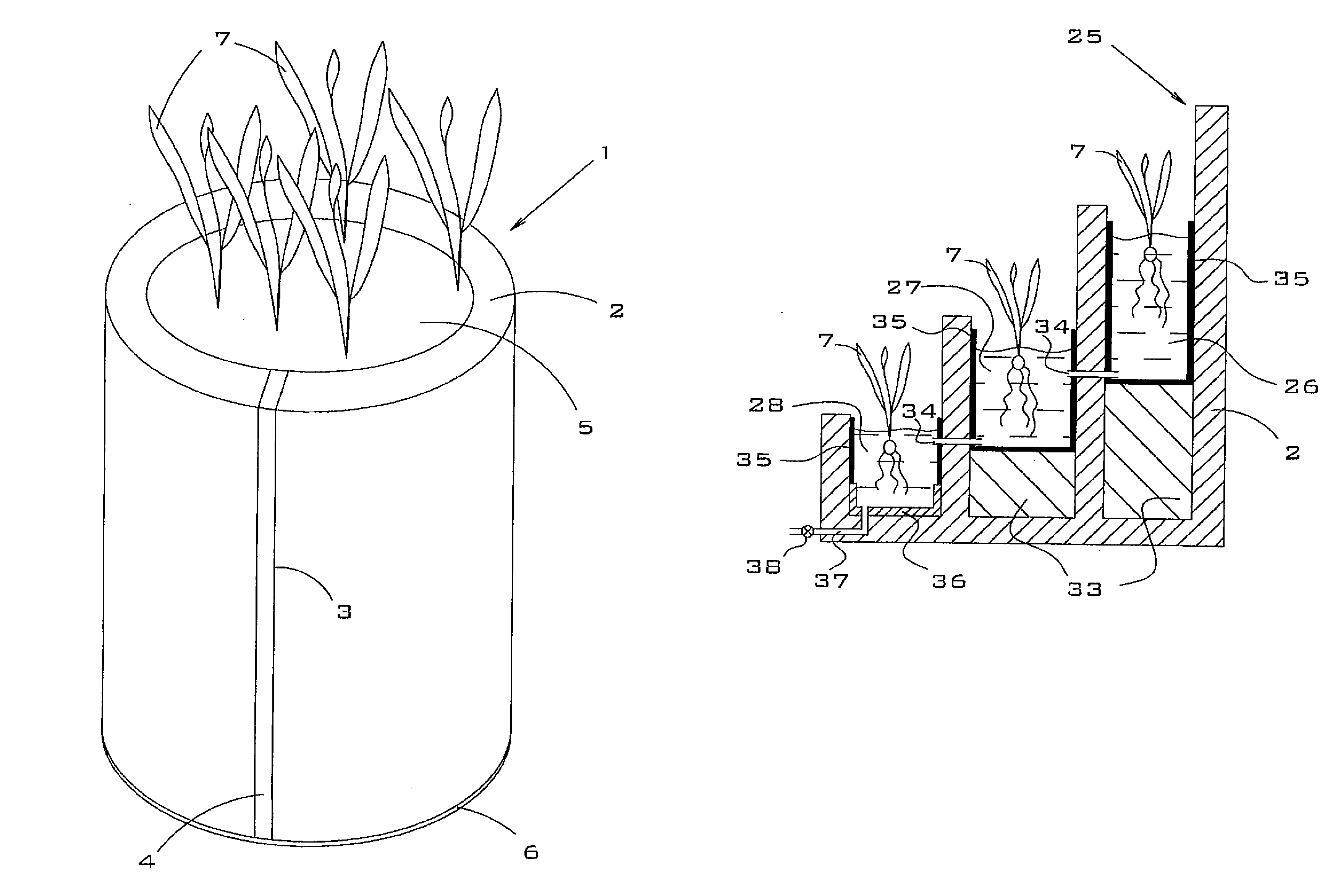
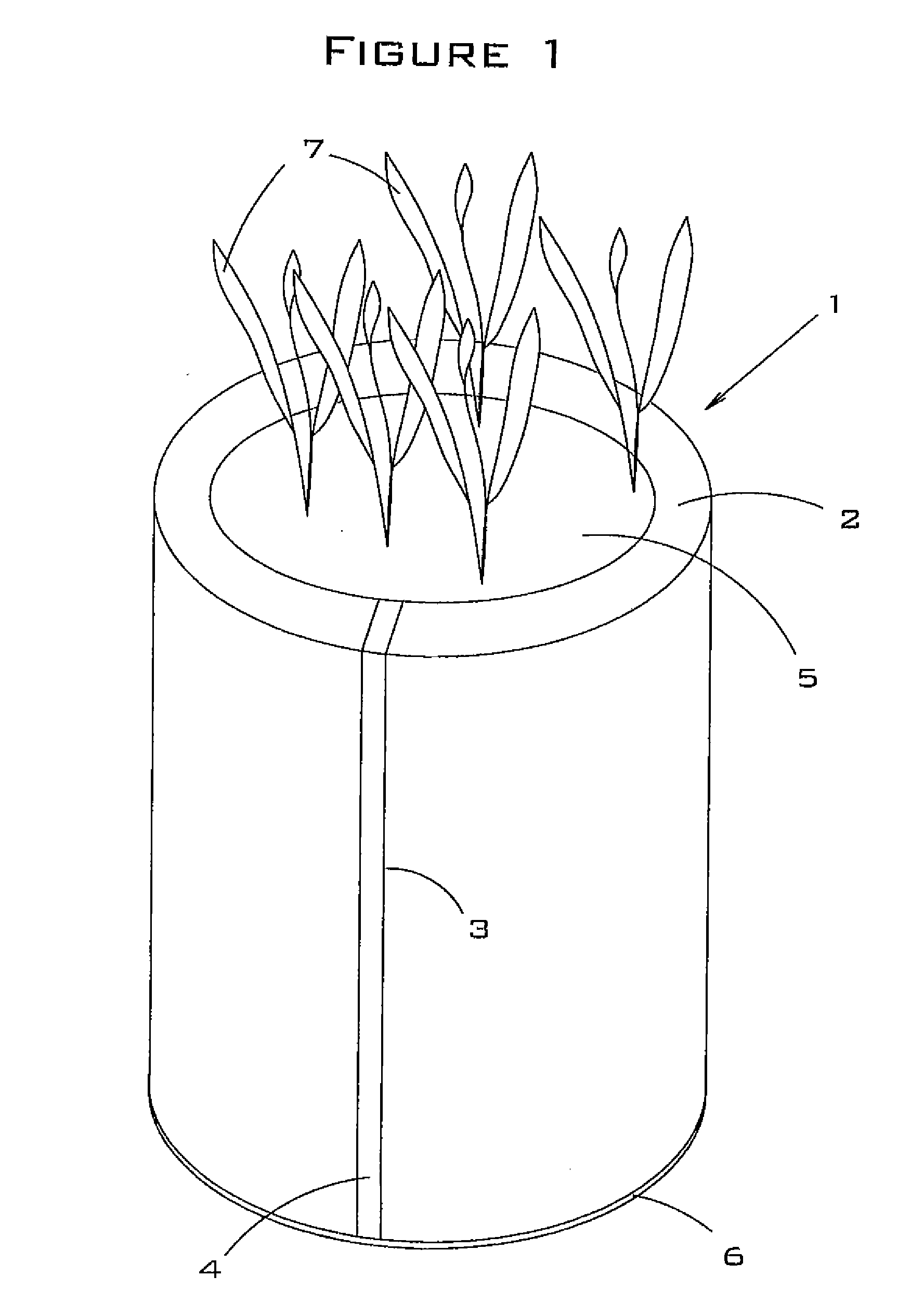
[0145]FIG. 1 is a perspective view of the present invention. In this embodiment, the raised bed planter 1 is comprised of an exoskeleton 2 with a seam 3, bonding agent 4, interior fill 5, and a bottom layer 6. Plants 7 are shown growing within the raised-bed planter 1. Bonding agent 4 is used to connect and seal the adjoining edges of exoskeleton 2.

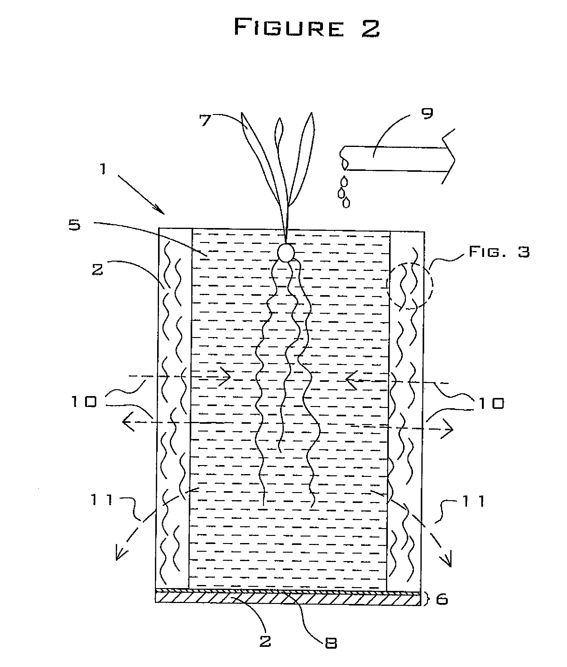
[0146]FIG. 2 is a cross-section side view of the first embodiment of the present invention, which shows the raised-bed planter 1 comprised of an exoskeleton 2, interior fill 5, plants 7, a bottom layer 6 comprising a weed barrier 8, and a bonding agent (not shown) that bonds the bottom layer 6 to the exoskeleton 2. An external water supply 9 is used to supply water to the raised-bed planter 1. Arrows 10 represent gases that pass through the permeable exoskeleton 2 from the atmosphere to the interior fill 5 and from the interior fill 5 to the atmosphere. One of these atmospheric gases is oxygen, which is necessary for plant root survival. ...

second embodiment

[0154]FIG. 4 is a perspective view of the raised-bed planter 1, in which the planter is comprised of a short outer section 17 and a long inner section 18. Each individual section 17 and 18 is similar to the embodiment shown in FIG. 1 in that it is comprised of an exoskeleton 2 and interior fill 5. This embodiment is advantageous for certain applications because it provides for two growing environments, thereby allowing different types of plants to be grown simultaneously. For example, the outer section 17 may be heavily watered to support wetland plants, while the inner section 18 may be lightly watered to support desert plants. This embodiment also comprises an optional impermeable bottom cup 19 around the bottom portion of the outer section 17. The purpose of the bottom cup 19 is to provide a zone of water-saturated soil in the bottom of the outer section 17, which may be desirable for some plants that prefer a saturated root zone. The bottom cup 19 may alternately be installed wi...


PUM


Abstract

A raised bed planter comprising a porous and permeable load-bearing exoskeleton comprised of nonwoven polymer matting and a spray-on polymer coating; a core section comprised of hydrophilic bedding fill material; and a bottom layer that serves as a weed barrier. The planter optionally incorporates multiple bedding levels and / or a wicking system or wicking components. In an alternate embodiment, the exoskeleton is comprised of a layer of outdoor carpet, a layer of fencing material, and a layer of nonwoven polymer matting. The planter optionally comprises one or more wings and a removable greenhouse cover.

Description

CROSS-REFERENCE TO RELATED APPLICATION [0001]This application claims priority under 35 U.S.C. §119(e) back to U.S. Patent Application No. 61 / 056,271 filed on May 27, 2008 and U.S. Patent Application No. 61 / 103,558 filed on Oct. 7, 2008.BACKGROUND OF THE INVENTION[0002]1. Field of the Invention[0003]The present invention relates generally to the field of horticulture, and more specifically, to a raised bed planter for growing edible and decorative plants above natural ground level.[0004]2. Description of the Related Art[0005]Traditional planters are limited in that their designs are usually fairly rigid (for example, they do not allow for freeform shapes, nor do they allow for large and / or interlocking shapes), the structures of the planters may not be portable or durable, and they do not adequately deal with drainage of excess moisture. Furthermore, the interior fill of most prior art planters does not provide for moisture retention and wicking. Examples of prior art planters are di...

Claims


Application Information

Patent Timeline
IPC IPC(8): A01G9/02A01G25/00A01G25/16A01G13/02
CPCA01G9/023A01G13/10A01G13/0212A01G9/02
Inventor KANIA, BRUCE G.STEWART, FRANK M.
Owner FOUNTAINHEAD
Features
  • Generate Ideas
  • Intellectual Property
  • Life Sciences
  • Materials
  • Tech Scout
  • Unparalleled Data Quality
  • Higher Quality Content
  • 60% Fewer Hallucinations
Learn More