Optical glass, glass material for press molding, optical element blank, optical element and manufacturing method thereof
a technology of optical glass and press molding, which is applied in the field of optical glass, can solve the problems of difficult to obtain glass having a high degree of optical homogeneity from fluorophosphate glass, difficult to obtain glass having a high degree of thermal stability, and drawbacks of low dispersion glass, so as to suppress glass volatility, enhance thermal stability, and high refractive index
- Summary
- Abstract
- Description
- Claims
- Application Information
AI Technical Summary
Benefits of technology
Problems solved by technology
Method used
Image

Examples
first example
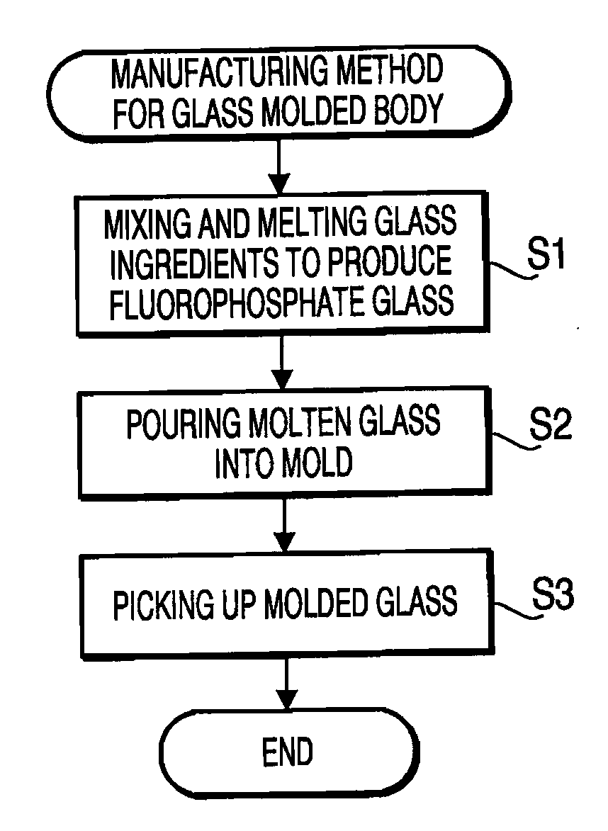
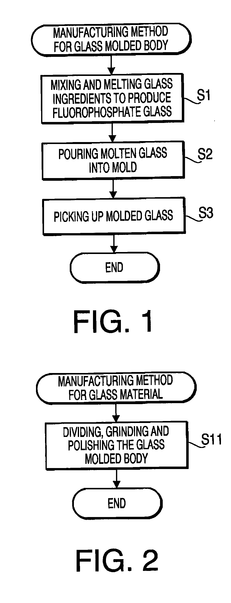
[0181]To achieve glass composition shown in Tables 1 to 3, various ingredients such as metaphosphate, fluoride and oxide are used, the ingredients are weighed, and the ingredients are mixed sufficiently. Then, the mixed ingredients are placed into a platinum melting pot, and are heated and melted. After melting, the molten glass is flowed into to a casting mold, and is cooled to the temperature near the glass transition temperature, and is immediately moved to an annealing furnace to perform the annealing for approximately one hour under the glass transition temperature range. Then, the glass is cooled in the furnace to the room temperature. Consequently, a plurality of pieces of optical glass No. 1 to 13 are obtained.
[0182]When an observer has inspected each obtained glass in an enlarged view with an optical microscope, the observer did not found separation of a crystal, foreign materials such as platinum particles, air bubbles and striaes. Each of Tables 1, 2, and 3 shows the prop...
second example
[0198]The glass ingredients (not containing carbonate) mixed to obtain each optical glass described in First Example are melted, clarified and homogenized to form molten glass, a drop of molten glass is dropped from the platinum nozzle to be received on a prefrom mold, and a spheric preform made of various types of glass is formed by floating the drop of molten glass by applying the wind pressure thereto.
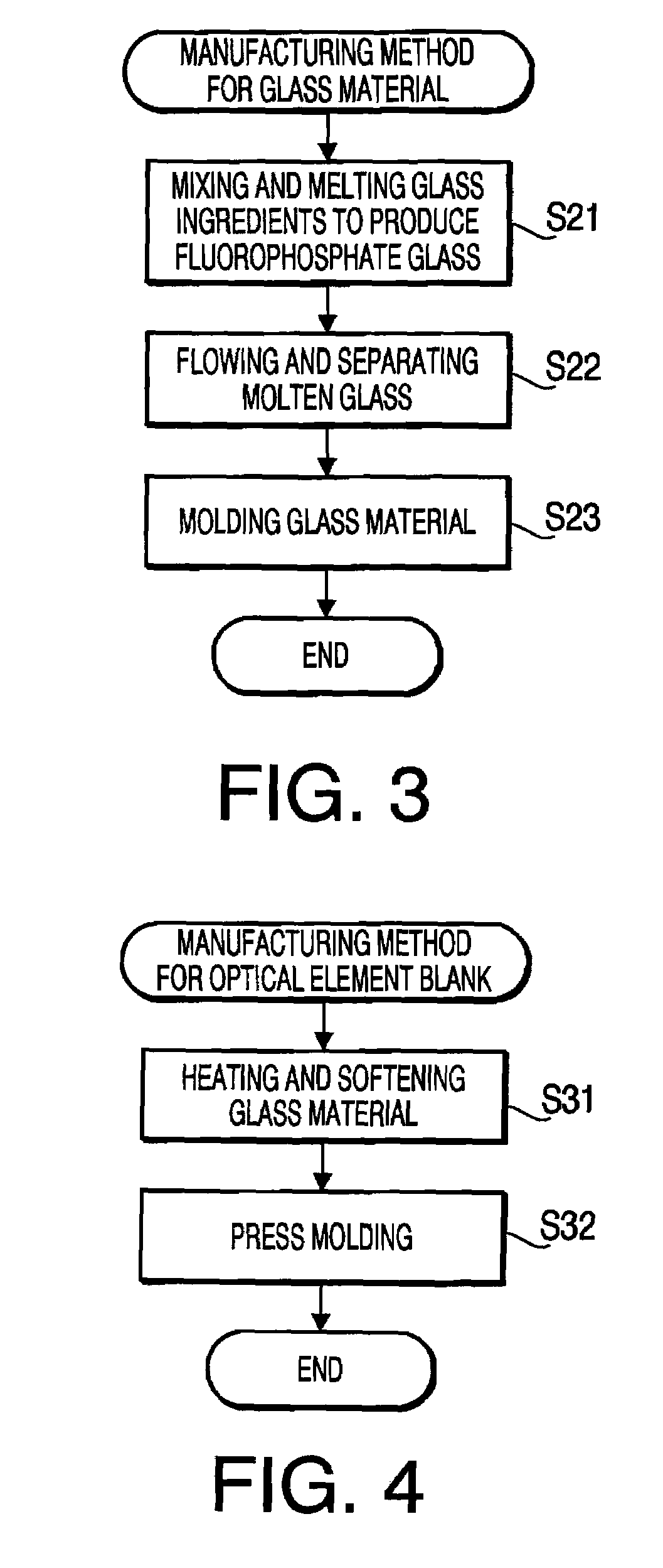
[0199]A preform made of various types of glass can be formed by continuously flowing the above described molten glass from the platinum pipe, receiving a lower end of the flowing molten glass on a preform mold, making a constriction at a portion of the flowing molten glass, and dropping the preform mold rapidly in a straight line to separate the molten glass at the position of the constriction. Further, the separated molten glass body is received on the preform mold, and then the preform is formed by floating the molten glass body by applying the wind pressure thereto. The observer ...
third example
[0200]A plurality of glass pieces are formed by introducing the continuously flowing molten glass (which is prepared in accordance with Second Example) to form a glass block, annealing the glass block, and thereafter cutting the glass block. The preform made of various types of glass is manufactured by grinding and polishing each glass piece. The observer did not find devitrification, striaes, foreign materials, and air bubbles in the inside of the thus obtained optical block (i.e., a portion to be used for the preform).
[0201]Since the thus obtained preform has a relatively low Abrasion and a relatively high Knoop hardness number as fluorophosphate glass, Abrasion during a process such as polishing is low, and therefore it is possible to enhance the surface processing accuracy and to prevent flaws from remaining on the surface of the preform.
PUM
| Property | Measurement | Unit |
|---|---|---|
| liquid phase temperature | aaaaa | aaaaa |
| molar ratio | aaaaa | aaaaa |
| molar ratio | aaaaa | aaaaa |
Abstract
Description
Claims
Application Information
 - R&D
- Intellectual Property
- Life Sciences
- Materials
- Tech Scout
- Unparalleled Data Quality
- Higher Quality Content
- 60% Fewer Hallucinations
Browse by: Latest US Patents, China's latest patents, Technical Efficacy Thesaurus, Application Domain, Technology Topic, Popular Technical Reports.
© 2025 PatSnap. All rights reserved.Legal|Privacy policy|Modern Slavery Act Transparency Statement|Sitemap|About US| Contact US: help@patsnap.com