
Method for Scalable Video Coding

a video coding and video coding technology, applied in the field of video coding scalable, can solve the problems of high complexity of motion estimation step, detection of efficiency loss, and limitation of performance during quantization step

Active Publication Date: 2009-12-10
TELECOM ITALIA SPA
View PDF3 Cites 90 Cited by
  • Summary
  • Abstract
  • Description
  • Claims
  • Application Information

AI Technical Summary

Benefits of technology

[0031]The Applicant has found that, by performing the optical flow computation for the lowest space resolution, followed by a similar process for greater resolutions with the addition of a constraint which measures the similarity between the solution for the considered level and the solution for the below level at a lower resolution, it is possible to obtain an improvement of estimating device performances.
[0035]It is therefore possible to make the solution more or less constrained to some space levels, in order to maximise performances depending on scene contents and scalability needs.

Problems solved by technology

With the advent of new video coding technologies, based on different transforms from the traditional DCT (Discrete Cosine Transform), such as the “wavelet” transform, an efficiency loss is detected due to the use of block matching as motion estimation technique.
Such components highly limit performances during the quantization step.
In scalable coders, in case of space scalability, the motion estimation step is highly complicated and performances are strongly affected by such step.
The optimum prediction for lower resolutions, in fact, is not always given by scaling of motion vectors computed at full resolution, due to the loss of details and the appearance of aliasing.
It is therefore impossible to determine the optimum motion for all resolutions by exclusively computing it in a limited set thereof.
The block matching, however, has difficulties if applied to the scalable coding, since it is not known how to realise motion fields which are able to faithfully represent different space resolutions.

Method used


Image

  • Method for Scalable Video Coding
  • Method for Scalable Video Coding
  • Method for Scalable Video Coding

Examples


Embodiment Construction

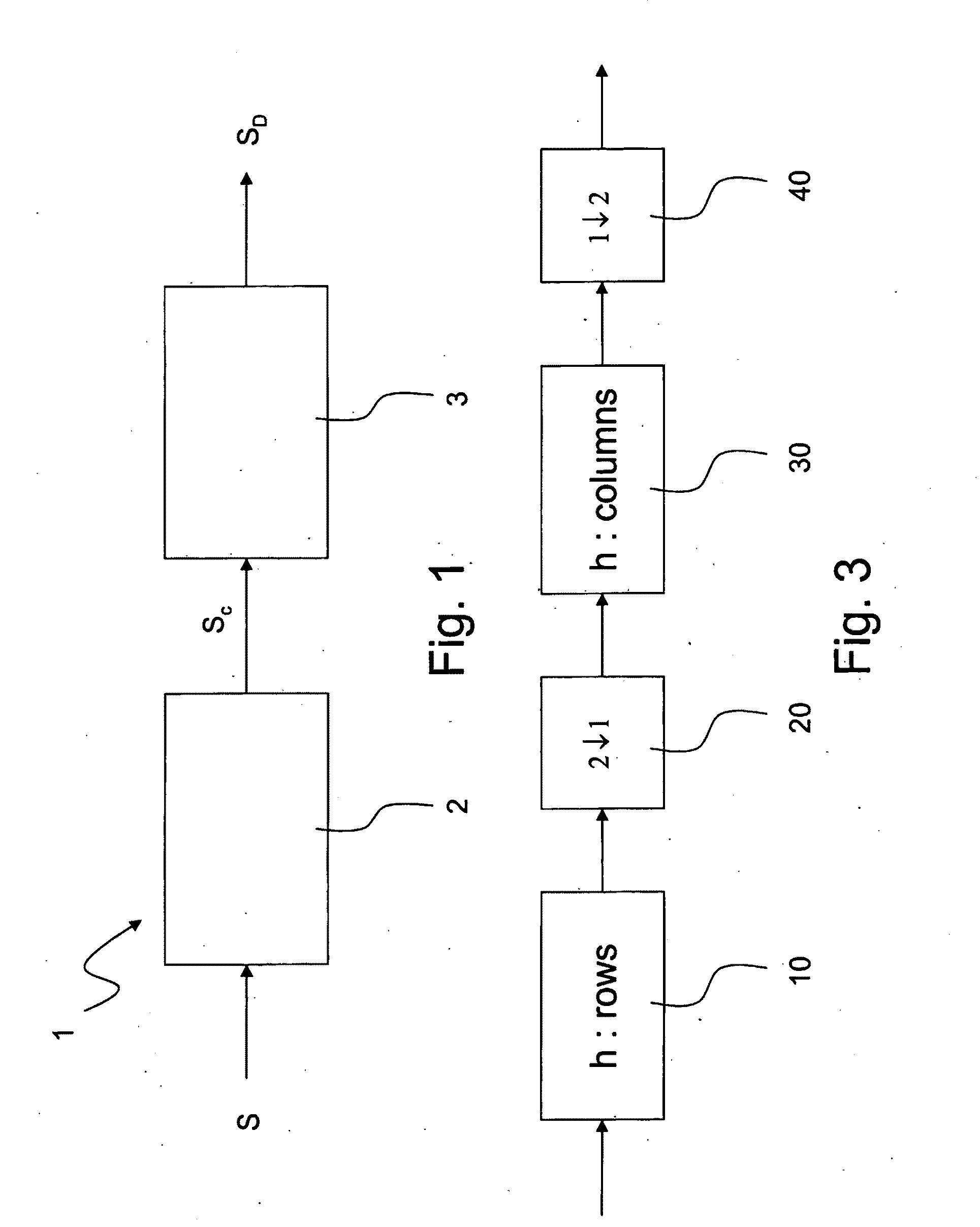
[0071]With reference to FIG. 1, 1 designates a system for transmitting video signals, comprising an image coder 2 and an image decoder 3. The image coder 2 is adapted to receive a video signal S generated by a video filming device (such as a digital video camera), to code the signal S for generating a corresponding coded video signal Sc, and finally to transmit such coded signal on a transmitting medium 4 of a known type, for example an optical fiber connection. The decoder 3 is adapted to receive the coded signal Sc and to decode such signal to extract a signal SD, similar but not necessarily equal to signal S.

[0072]The signal S is coded so that it can be decoded on a space resolution level chosen among a set of possible resolution levels.

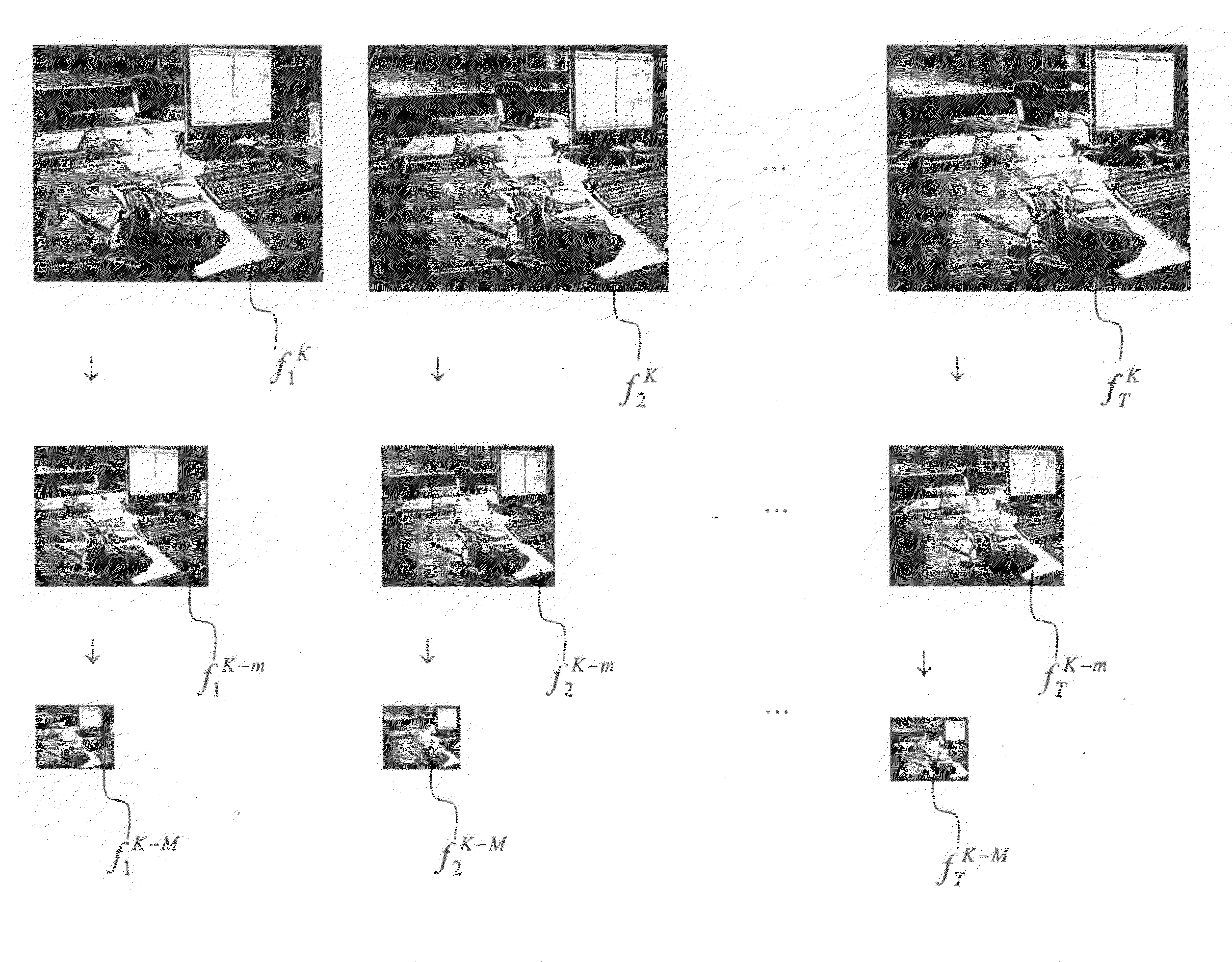
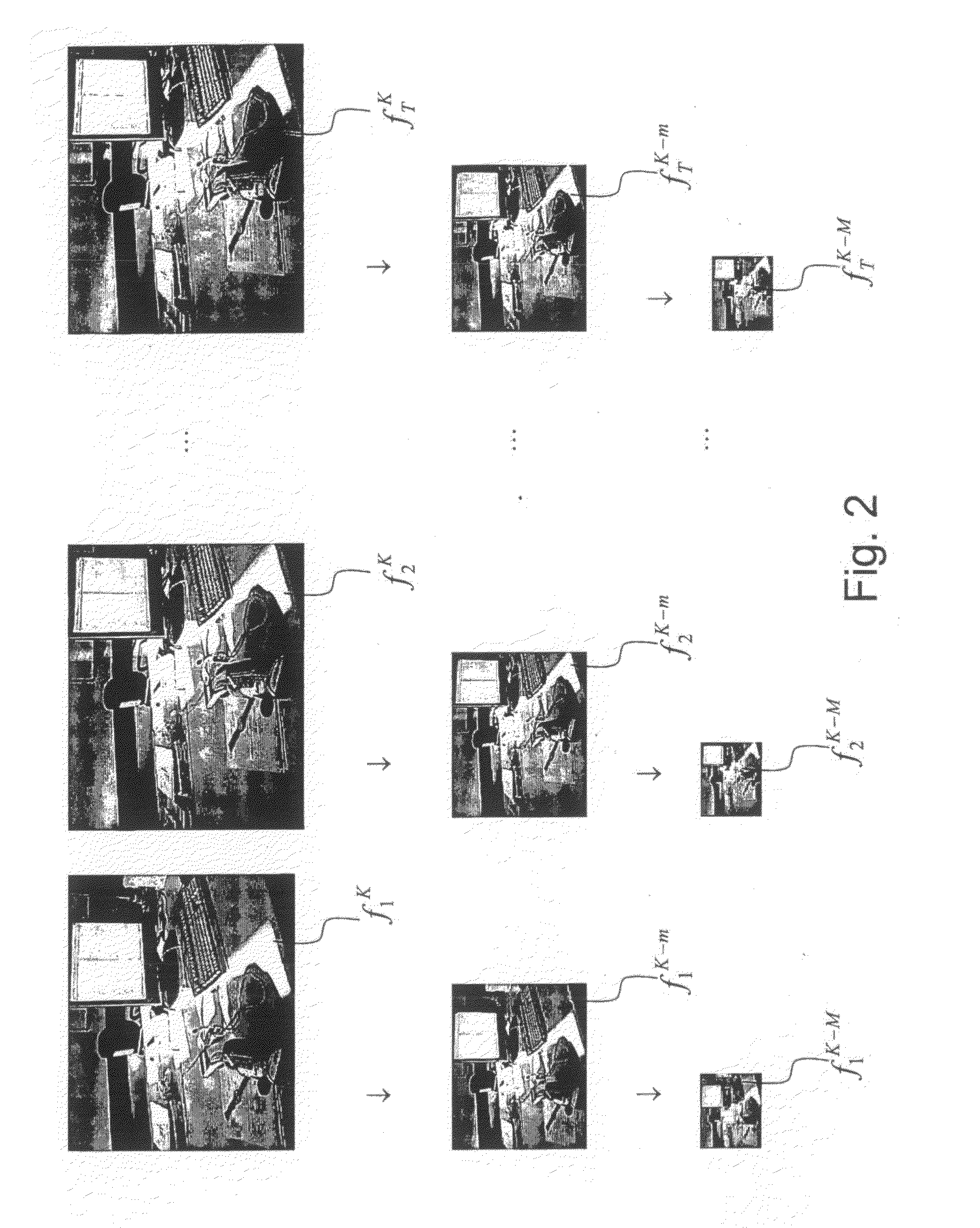
[0073]In the following description, therefore, the presence of a multi-resolution pyramid will be assumed for representing photograms and motion fields having M+1 levels, in which the highest level has index K and the lowest has index K−M.

[0074]FI...


PUM


Abstract

A method for estimating motion for the scalable video coding, includes the step of estimating the motion field of a sequence of photograms which can be represented with a plurality of space resolution levels including computing the motion field for the minimum resolution level and, until the maximum resolution level is reached, repeating the steps of: rising by one resolution level; extracting the photograms for such resolution level; and computing the motion field for such resolution level. The motion field is computed through an optical flow equation which contains, for every higher level than the minimum resolution level, a regularization factor between levels which points out the difference between the solution for the considered level and the solution for the immediately lower resolution level. A more or less high value of the regularization factor implies more or less relevant changes of the component at the considered resolution during the following process iterations.

Description

TECHNICAL FIELD[0001]The present invention deals with a method for scalable video coding.[0002]Video coding is a complex procedure, composed of a chain of different operations; motion estimation, space transform, quantization, entropy coding. The first operation, motion estimation, plays a major role in the process, and its efficiency deeply affects the obtainable compression ratio. During such step, in fact, a prediction of the contents of a photogram is computed starting from the adjacent ones, exploiting the high similarity which usually distinguishes subsequent photograms.[0003]Herein below, the term “reference photogram” means an already processed photogram so that it can be reconstructed by the decoder. The term “current photogram” means the photogram to be coded, namely the processing object. The reference photogram is modified in order to approximate the current photogram.[0004]The similarity between subsequent photograms can be expressed through “distortions”. The coded flo...

Claims


Application Information

Patent Timeline
IPC IPC(8): H04N7/12
CPCH04N19/537H04N19/53
Inventor CORDARA, GIOVANNIFRANCINI, GIANLUCALEPSOY, SKJALG
Owner TELECOM ITALIA SPA
Learn More