Antenna apparatus utilizing small loop antenna element having munute length and two feeding points

a technology of antenna elements and antenna supports, which is applied in the direction of loop antennas, polarised antenna unit combinations, antenna supports/mountings, etc., can solve the problems of reducing communication quality, affecting the effect of fading on the antenna, and affecting the accuracy of distance measurement, so as to prevent the degradation of communication quality and increase the communication quality. , the effect of constant gain

Inactive Publication Date: 2009-12-24
PANASONIC CORP
View PDF20 Cites 79 Cited by
  • Summary
  • Abstract
  • Description
  • Claims
  • Application Information

AI Technical Summary

Benefits of technology

[0025]Therefore, according to the antenna apparatus of the present invention, an antenna apparatus capable of obtaining a substantially constant gain and preventing the degradation in the communication quality regardless of the distance between the antenna apparatus and the conductor plate can be provided. Moreover, an antenna apparatus that obtains a communication quality higher than that of the prior art can be provided by increasing the antenna gain of the polarized wave component radiated from the connecting conductor while suppressing the decrease in the antenna gain of the polarized wave component radiated from the sm

Problems solved by technology

Moreover, when it is used in a multipath environment, the antenna suffers an influence of fading.
Consequently, a relation between the distance and the received field intensity such that the received field intensity decreases as the distance

Method used


Image

  • Antenna apparatus utilizing small loop antenna element having munute length and two feeding points
  • Antenna apparatus utilizing small loop antenna element having munute length and two feeding points
  • Antenna apparatus utilizing small loop antenna element having munute length and two feeding points

Examples


first preferred embodiment

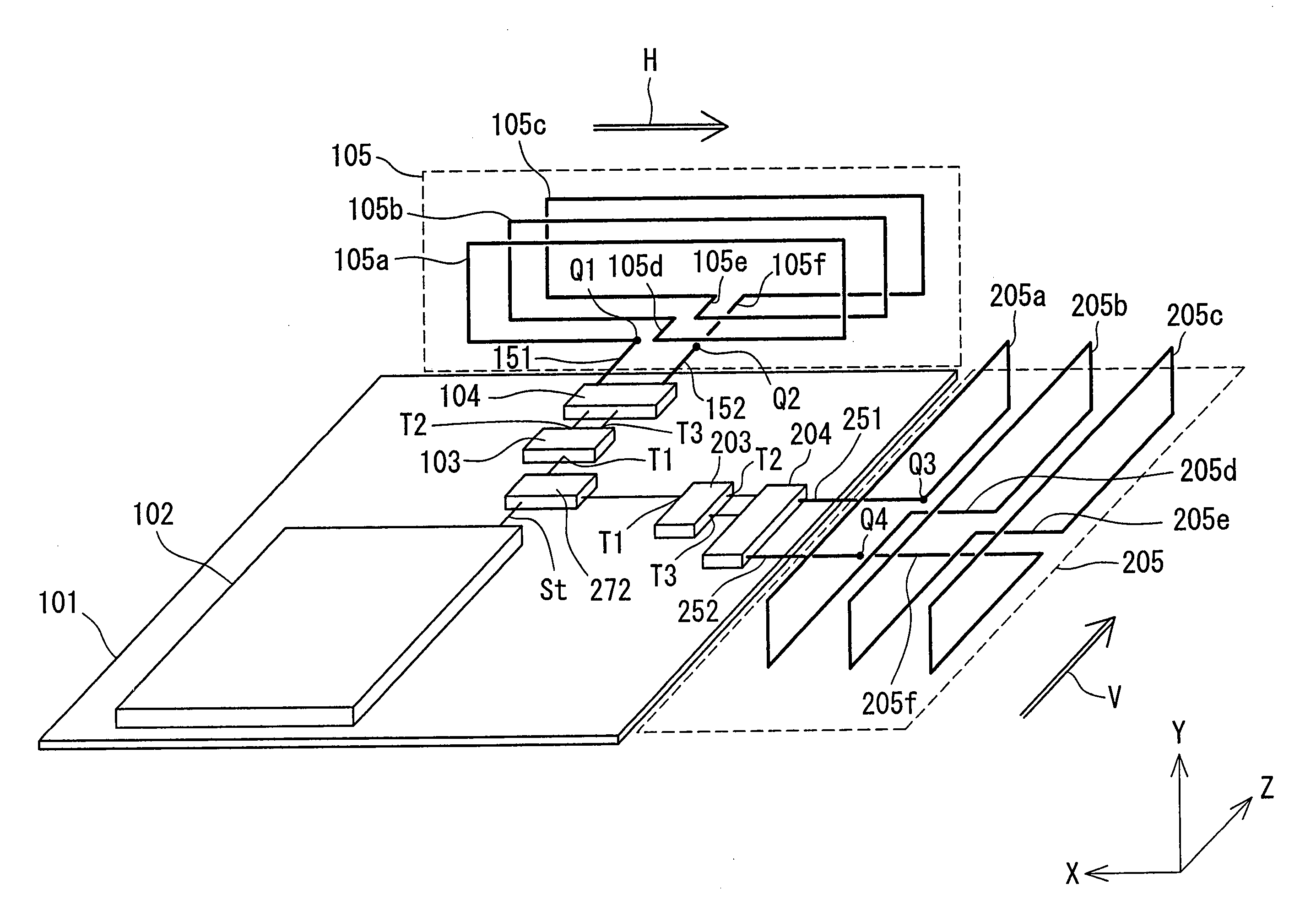
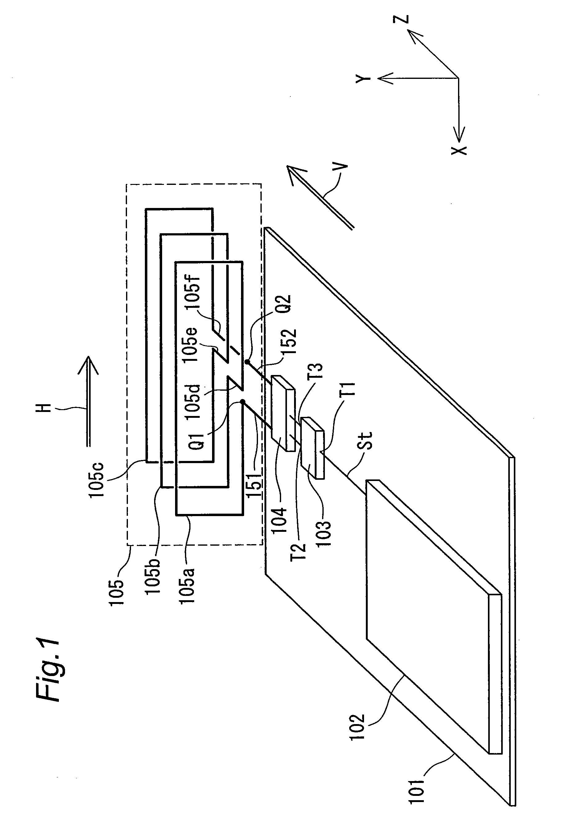
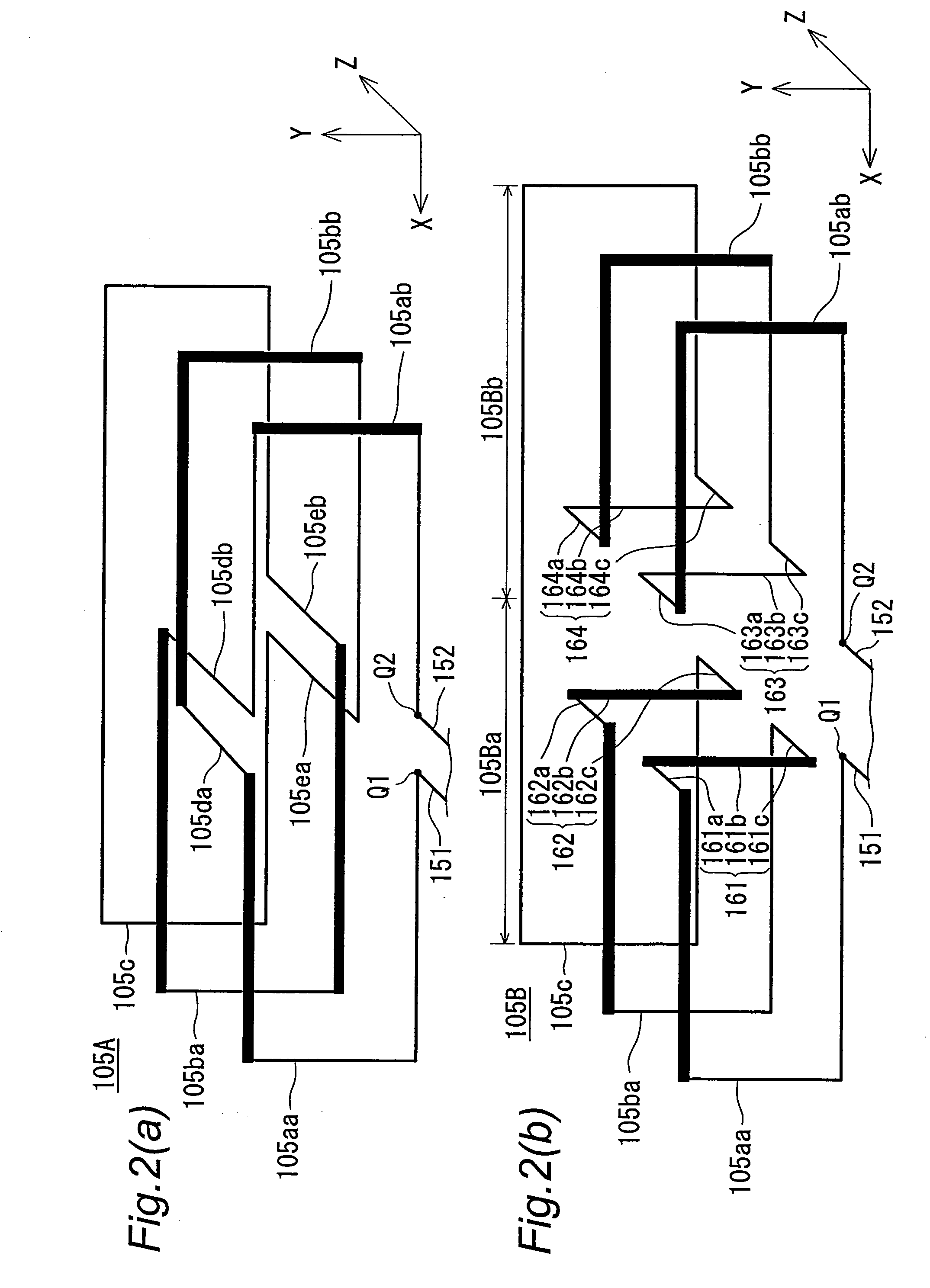
[0186]FIG. 1 is a perspective view showing a configuration of an antenna apparatus having a small (or minute) loop antenna element 105 according to the first preferred embodiment of the invention. In FIG. 1 and subsequent figures, directions are expressed by a three-dimensional XYZ coordinate system. In this case, the longitudinal direction of a grounding conductor plate 101 is set to the Z-axis direction, its widthwise direction is parallel to the X-axis direction, and a direction perpendicular to the plane of the grounding conductor plate 101 is set to the Y-axis direction. Moreover, in FIG. 1 and the subsequent figures, the direction or the antenna gain of the horizontally polarized wave component is indicated by H, and the direction or the antenna gain of the vertically polarized wave component is indicated by V. Further, St represents an unbalanced transceiving signal containing a transmitted wireless signal and a received wireless signal.

[0187]Referring to FIG. 1, a wireless t...

second preferred embodiment

[0228]FIG. 10 is a perspective view showing a configuration of an antenna apparatus having small loop antenna elements 105 and 205 according to the second preferred embodiment of the invention. The antenna apparatus of the second preferred embodiment differs from the antenna apparatus of the first preferred embodiment of FIG. 1 in the following points.

[0229](1) A small loop antenna element 205, which has a configuration similar to that of the small loop antenna element 105 and is provided orthogonal to the small loop antenna element 105, is further provided.

[0230](2) A switch 208, a feeder circuit 203 and an impedance matching circuit 204 are further provided.

[0231](3) The grounding conductor plate 101 preferably has a substantially square shape.

[0232]The points of difference are described below in detail.

[0233]Referring to FIG. 10, the small loop antenna element 205 is provided so that the formed loop plane becomes substantially perpendicular to the plane of the grounding conductor...

third preferred embodiment

[0245]FIG. 13 is a perspective view showing a configuration of an antenna apparatus having small loop antenna elements 105 and 205 according to the third preferred embodiment of the invention. The antenna apparatus of the third preferred embodiment differs from the antenna apparatus of the second preferred embodiment of FIG. 10 in the following point.

[0246](1) A 90-degree phase difference distributor 272 is provided in place of the switch 208.

[0247]The point of difference is described below. The 90-degree phase difference distributor 272 distributes a transmitted wireless signal from the wireless transceiver circuit 102 into two transmitted wireless signals that have a mutual phase difference of 90 degrees, outputs the same to the feeder circuits 103 and 203 and performs processing in the reverse direction for a received wireless signal.

[0248]Next, radio wave radiation of the antenna apparatus configured as above is described below. Wireless signals having a phase difference of 90 d...


PUM


Abstract

The small loop antenna element of the antenna apparatus includes loop antenna portions that have a predetermined loop plane and radiate a first polarized wave component parallel to the loop plane, and at least one connecting conductor that is provided in a direction orthogonal to the loop plane and connects the plurality of loop plane portions to radiate a second polarized wave component orthogonal to the first polarized wave component. In the case of the antenna apparatus located adjacent to a conductor plate, by making the maximum value of the antenna gain of the first polarized wave component and the maximum value of the antenna gain of the second polarized wave component substantially identical when the distance between the antenna apparatus and the conductor plate is changed, a composite component of the first and second polarized wave components are made substantially constant regardless of the distance.

Description

TECHNICAL FIELD[0001]The present invention relates to an antenna apparatus that employs small (or minute) loop antenna elements and to an antenna system that employs the antenna apparatus.BACKGROUND ART[0002]In recent years, development of personal authentication techniques by a wireless communication system has been promoted for securing an information security. In concrete, with wireless communication equipment carried by a user and wireless communication equipment provided for a physical object such as a personal computer, a portable telephone, a vehicle or the like, authentication is consistently performed by the wireless communication systems. When the physical object enters a certain range of peripheries of the user, control of the physical object is enabled. When the physical object goes out of the certain range of peripheries of the user, control of the physical object is disabled. In order to judge whether or not the physical object exists within the certain range of periph...

Claims


Application Information

Patent Timeline
IPC IPC(8): H01Q11/12
CPCH01Q1/243H01Q7/00H01Q25/00H01Q21/245H01Q21/24H01Q3/28H01Q3/30H01Q1/24
Inventor MIYASHITA, NORIHIROYOSHIKAWA, YOSHISHIGE
Owner PANASONIC CORP
Why Eureka
Try Eureka