

Multi-beam ion/electron spectra-microscope
- Summary
- Abstract
- Description
- Claims
- Application Information
AI Technical Summary
Benefits of technology
Problems solved by technology
Method used
Image

Examples
Embodiment Construction
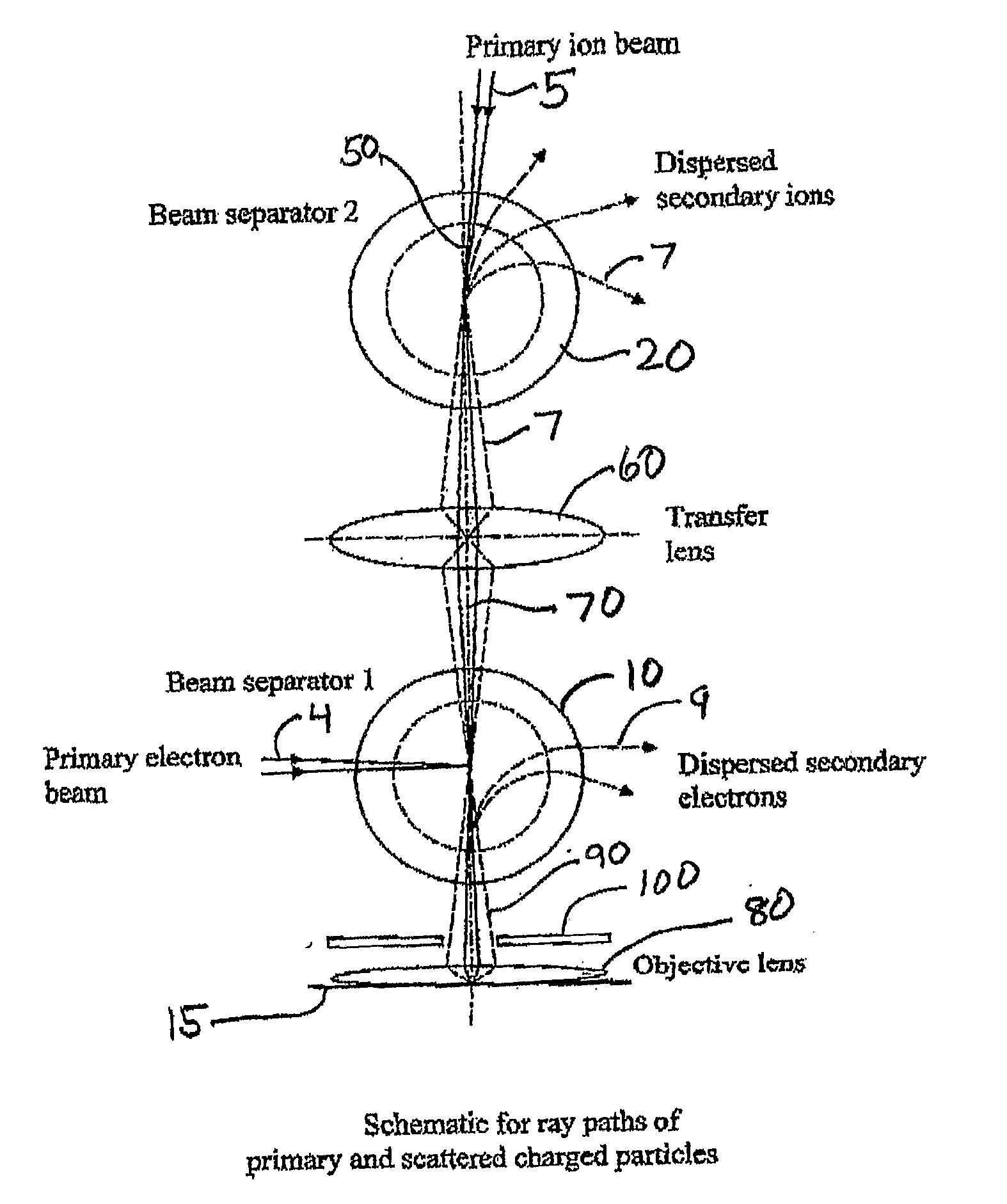
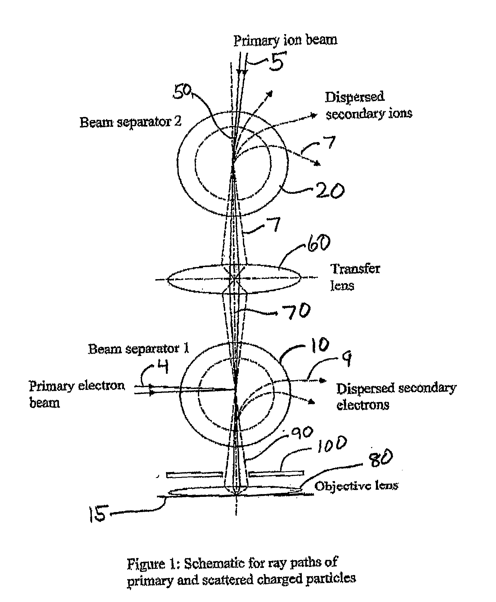
[0041]The present invention provides two embodiments of a multi-beam charged particle instrument that can simultaneously focus an electron beam and a variety of primary ion beams upon a material sample and can then analyze the energy / mass spectra of emitted electron and secondary ion species from the sample. In the following, we will describe the component elements of the instrument and indicate how they operate to fulfill the objects of the invention.
1. The Instrument
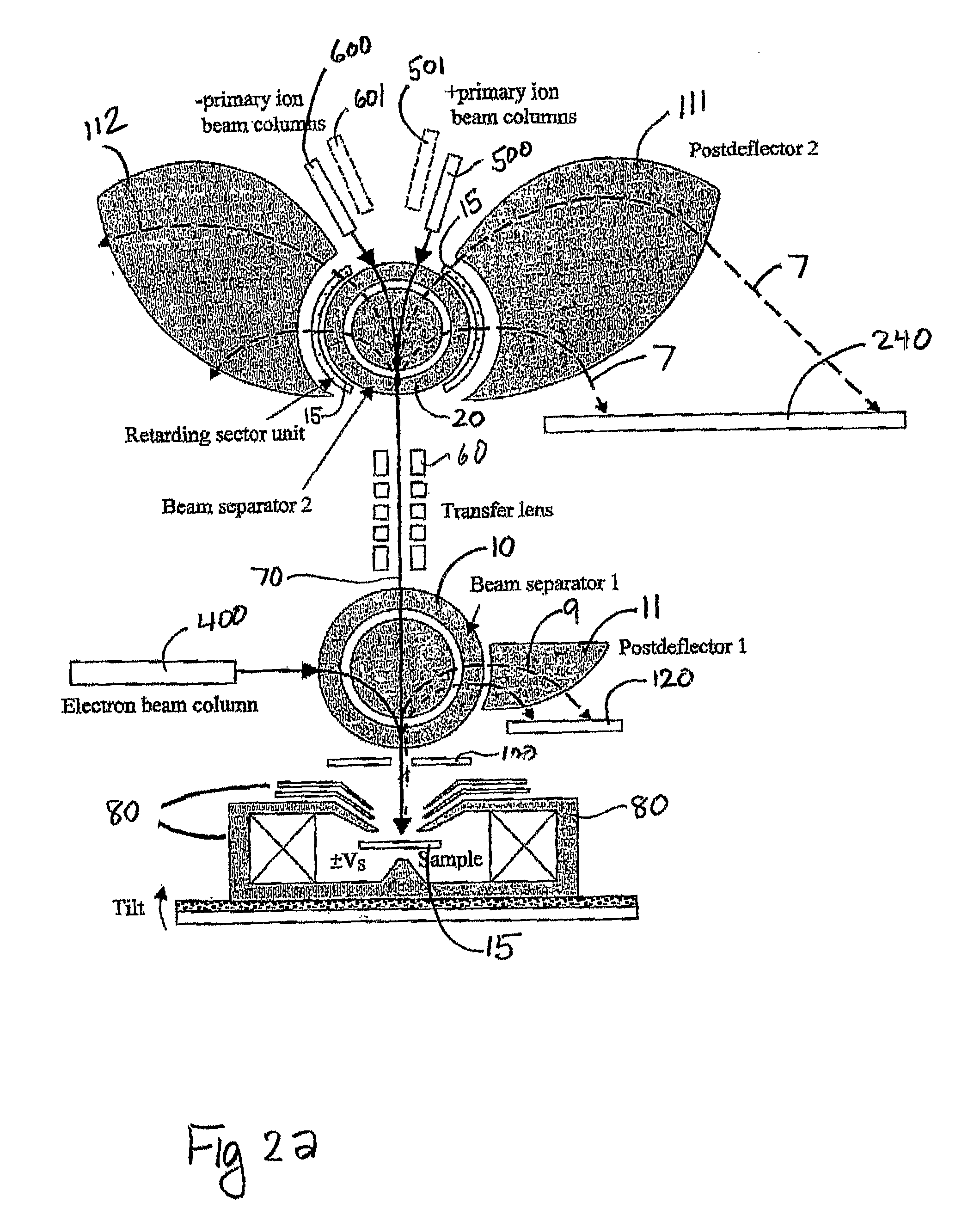
[0042]Referring now to FIG. 2a, there is shown the schematic of a first preferred embodiment of a dual electron / ion instrument that has a parallel (i.e., simultaneously operative) energy spectrometer for scattered electrons and a parallel mass spectrometer for secondary ions. The shaded area denotes parts of the instrument that are magnetic (contain magnetic fields to deflect moving charged particles). The SEM column (400), including e-gun, condenser lenses, scan unit, stigmator and aperture (not shown), directs an ele...
PUM
 Abstract
Description
Claims
Application Information