Discontinuous Conduction Mode Control Circuit and Method for Synchronous Converter

a control circuit and synchronous converter technology, applied in the direction of dc-dc conversion, power conversion systems, instruments, etc., can solve the problems of inefficiency, inability to meet the requirements of light load conditions, and still present problems with synchronous buck converters and efficiency, etc., to achieve efficient and reliable, enhance the efficiency of converter operations, and increase the efficiency of the converter in dcm

Active Publication Date: 2009-12-31
INFINEON TECH AUSTRIA AG
View PDF4 Cites 43 Cited by
  • Summary
  • Abstract
  • Description
  • Claims
  • Application Information

AI Technical Summary

Benefits of technology

[0029]These and other problems are generally solved or circumvented, and technical advantages are generally achieved, by preferred embodiments of the present invention which provide an efficient and reliable detection of the inductor current crossing the zero point in a synchronous DC-DC converter during DCM mode conditions, and the various embodiments provide control of the gating signals to increase the efficiency of the converter in DCM. The following summary is not an ex

Problems solved by technology

These inefficiencies may be tolerable if the load typically does not operate in a light load condition.
However, for situations where the load is often operated in a light load condition, for example for a microprocessor that has a “sleep” or standby mode, these inefficiencies are not acceptable.
However, the light load condition still presents problems with the synchronous buck converter and efficiency. FIG. 2 depicts the current (inductor current IL) and voltage (taken at the middle node labeled “phase” in FIG. 1(b) in the light load current or DCM mode of operation in a synchronous buck converter.
However, present approaches to controlling the turn off time of the SR are sensitive to delays in th

Method used


Image

  • Discontinuous Conduction Mode Control Circuit and Method for Synchronous Converter
  • Discontinuous Conduction Mode Control Circuit and Method for Synchronous Converter
  • Discontinuous Conduction Mode Control Circuit and Method for Synchronous Converter

Examples


Embodiment Construction

[0050]The making and using of the presently preferred embodiments are discussed in detail below. It should be appreciated, however, that the present invention provides many applicable inventive concepts that can be embodied in a wide variety of specific contexts. The specific embodiments discussed are merely illustrative of specific ways to make and use the invention, and do not limit the scope of the invention.

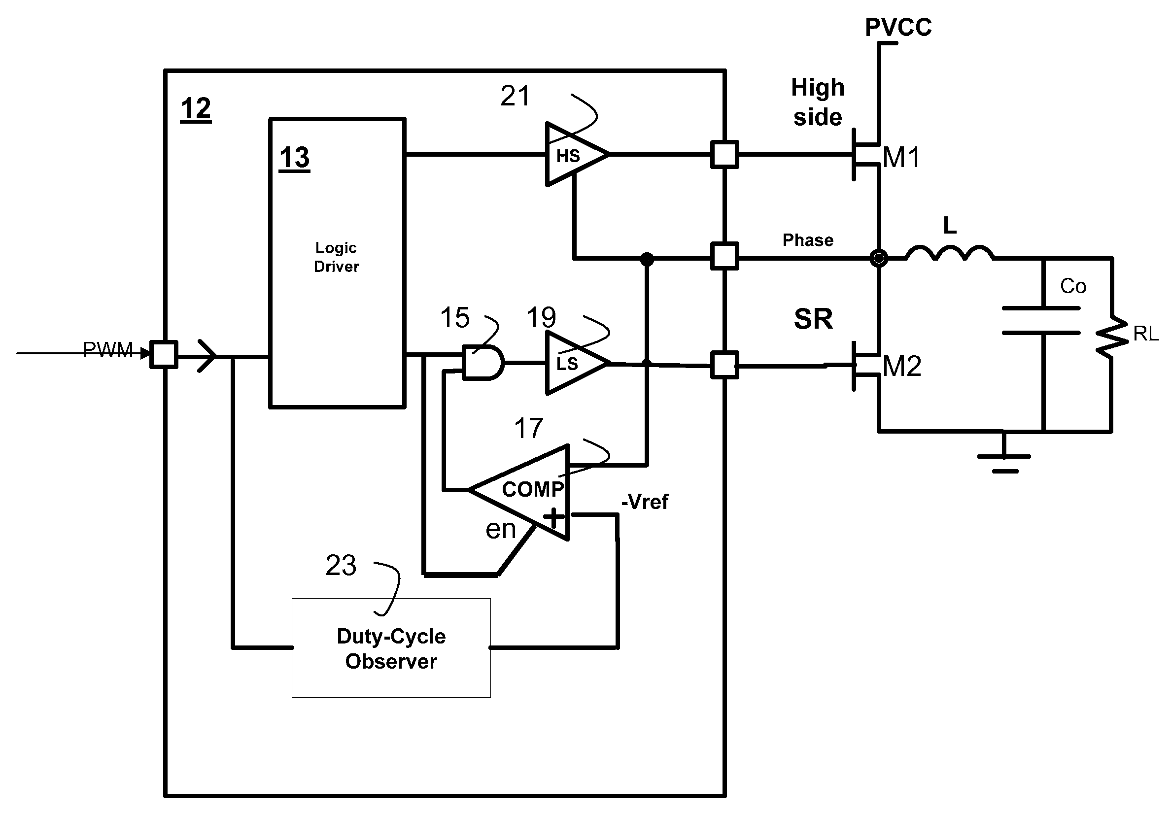
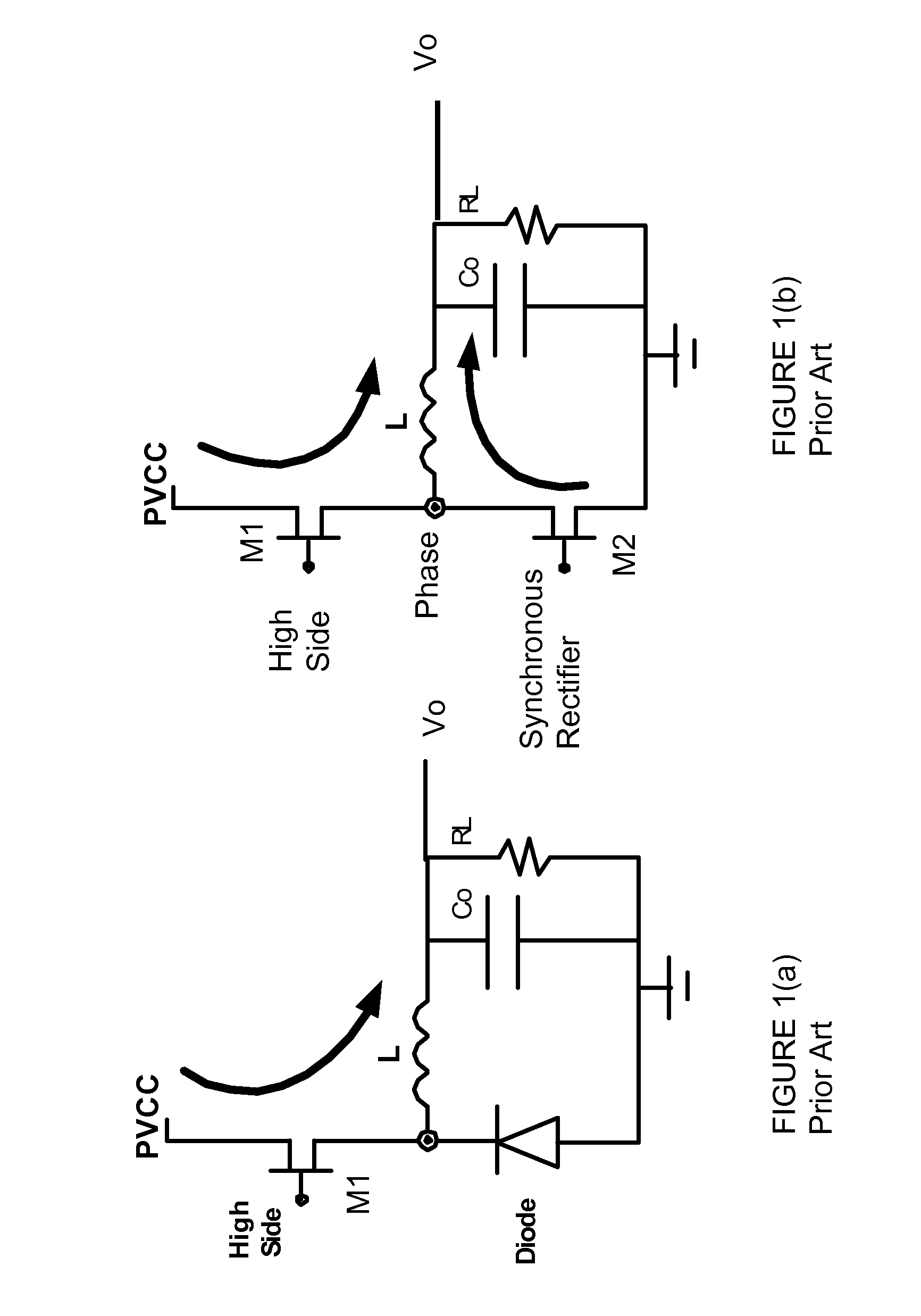
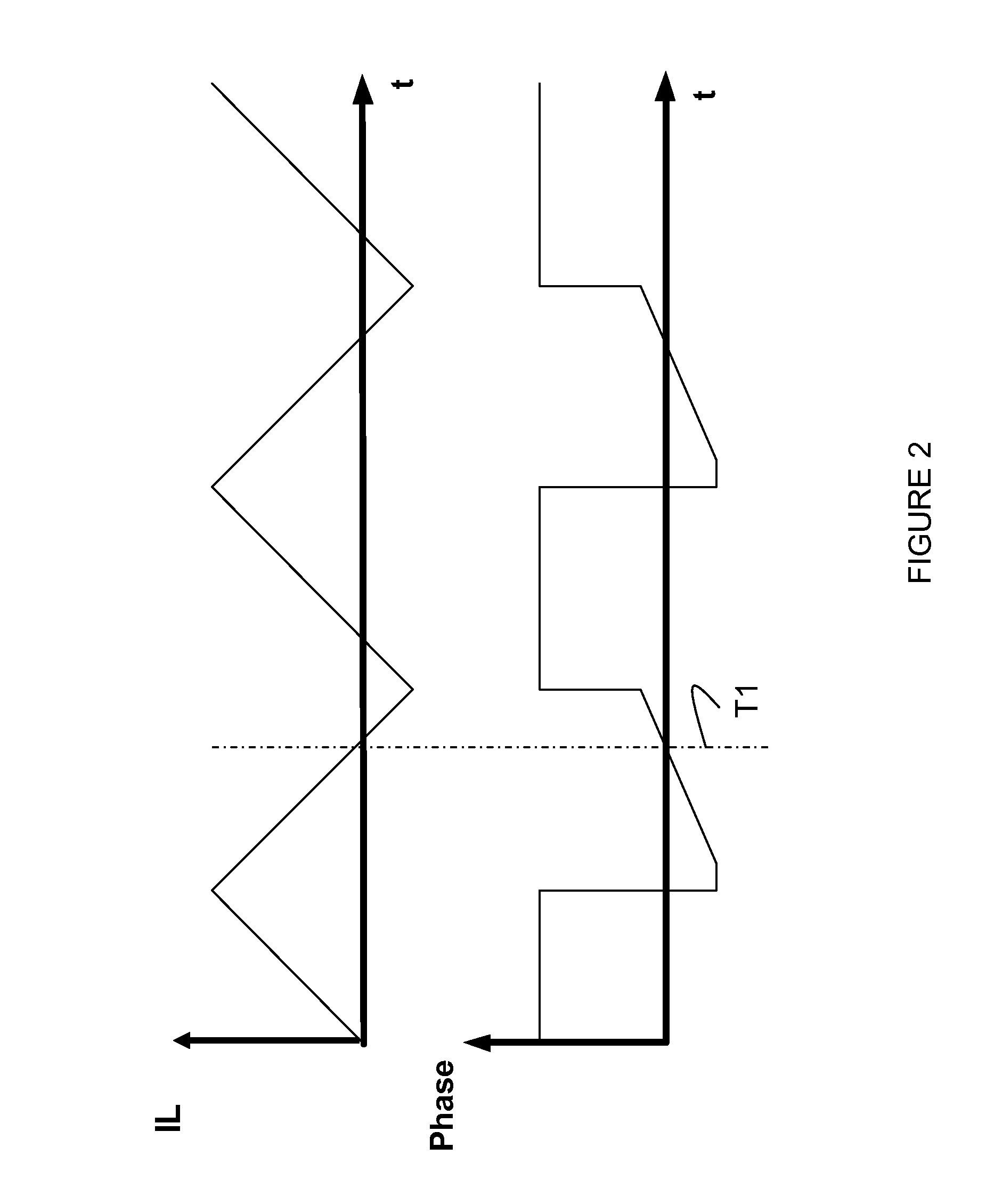
[0051]The present invention will now be described with respect to preferred embodiments in an illustrative, non-limiting, specific context, namely the DCM operation mode for a synchronous buck switching power converter. The invention may also be applied, however, to other circuits where a zero crossing detection is used, such as a boost, or buck-boost, a synchronous rectifier and the like that is used with a coil or inductor. In these exemplary circuit embodiments, a zero crossing detection may be used to control the switching of one or more drivers when the circuit is operat...


PUM


Abstract

Circuit and method for controlling a synchronous power converter in discontinuous conduction mode with increased efficiency is disclosed. Circuitry is provided outputting gating signals to a high side driver and a synchronous rectifier responsive to a pulse width modulated input signal, an inhibit circuit for inhibiting the gating signal to the synchronous rectifier upon detection of a zero crossing condition; a comparator receiving a measured circuit value from the synchronous converter and a reference value and outputting a zero crossing condition; and a duty cycle observer circuit for determining the average duty cycle of the pulse width modulated input signal and for varying the reference value. A method is disclosed determining if the average duty cycle in the pulse width modulated input signal is increasing in response to varying a reference value, and inhibiting a synchronous rectifier control signal when the comparator indicates a zero crossing condition.

Description

TECHNICAL FIELD[0001]The present invention relates generally to a system and method to improve the operation of power supply circuits such as are used in a switched mode power supply converter including multiphase power converters and DC-DC converters, and more particularly to a system and method for efficient operation of a DC-DC converter circuit using diode emulation during discontinuous conduction mode (“DCM”) which occurs during light load current operation.BACKGROUND[0002]Generally, buck power converters or buck regulators are used to generate power outputs for microelectronic devices. Although other converter topologies such as boost, buck boost, and the like are available, buck converters are often used because the buck converter topology is relatively efficient and provides high current swing (di / dt) capability. When providing a microelectronic circuit such as a microprocessor, for example, with a regulated voltage, current swing di / dt and response time are very important c...

Claims


Application Information

Patent Timeline
IPC IPC(8): H02M3/335
CPCH02M3/3376H02M3/156
Inventor GALVANO, MAURIZIOBERNACCHIA, GIUSEPPECAPODIVACCA, GIOVANNI
Owner INFINEON TECH AUSTRIA AG
Why Eureka
Try Eureka