
Toner, and method for producing the same

Inactive Publication Date: 2009-12-31
RICOH KK
View PDF10 Cites 25 Cited by
  • Summary
  • Abstract
  • Description
  • Claims
  • Application Information

AI Technical Summary

Benefits of technology

[0012]The present invention aims to provide a toner that is small in particle size and achieves shape irregularity of toner particles, i.e. formation of irregularly shaped toner particles, while the toner is produced by atomizing and Jetting a toner composition liquid in a vapor phase without using an aqueous medium containing a dispersant, which may impair the electrostatic property, and is excellent in blade cleanability, as well as to provide a method for producing a toner.
[0013]Further, the present invention also aims to provide a toner capable of obtaining excellent blade cleanability in a stable manner because the toner has non-spherical shape and is composed of particles having monodispersibility in unprecedented grain size, and thus the toner has an extremely less amount of fine powder which could degrade blade cleanability as well as to provide a method for producing a toner.
[0032]According to the present invention, a toner having a small particle size and capable of obtaining high quality images can be efficiently produced with low energy, and the present invention can provide a toner capable of stably obtaining superior blade cleanability to those of conventional toners having a small particle size, and can provide a method for producing a toner.

Problems solved by technology

In order to remove such residual toner, blade cleaning devices, which are simple in structure and enable obtaining favorable cleanability, are frequently used, however, it is known that the smaller a toner particle size and the closer a toner to a spherical shape, the more difficult it is to remove the toner from a surface of a latent electrostatic image bearing member.
However, in recent years, to obtain high-quality images, toners tend to become smaller in size.
Therefore, when a toner is made to have a small particle size of 6 μm or less with the use of such a pulverization method, the pulverization efficiency is reduced and the production loss is increased, resulting in a low productivity and high costs.
Whereas, in these methods, toner particles are formed and produced in an aqueous medium, and thus it is necessary to dry water, which has a large amount of latent heat of vaporization, and a large amount of energy for drying is required.
Further, it has been known that these methods assume that a dispersant is used in an aqueous medium, and thus such a dispersant that may impair the electrostatic property of a toner remains on a surface of the toner, causing problems such as adverse effects on environmental stability.
Further, in order to remove the dispersant, a great amount of washing water is required.
For this reason, toners produced by these methods and these toner production methods are still far from satisfaction.
However, these methods have shortcomings that the number of liquid droplets that can be ejected from one nozzle per unit of time is limited, resulting in poor productivity, and it is difficult to prevent the particle size distribution from widening due to coalescence of liquid droplets and therefore the method is also far from satisfaction in terms of monodispersibility.
Furthermore, a toner that can be obtained by the method is also disadvantageous in that toner particles are formed in spherical shape due to the surface tension of the toner composition liquid used.

Method used


Image

  • Toner, and method for producing the same
  • Toner, and method for producing the same
  • Toner, and method for producing the same

Examples


example 1

Preparation of Colorant Dispersion Liquid

[0195]First, as a colorant, a dispersion liquid of carbon black was prepared.

[0196]Specifically, 17 parts by mass of carbon black (REGAL 400, manufactured by Cabot Corp.) and 3 parts by mass of a pigment dispersant were added to 80 parts by mass of ethyl acetate and primarily dispersed using a mixer having stirring blades to obtain a primary dispersion liquid. As the pigment dispersant, AJISPER PB821 (manufactured by Ajinomoto Fine-Techno Co., Inc.) was used. The obtained primary dispersion liquid was finely dispersed under strong shearing force using a DYNO MILL to prepare a second dispersion liquid where aggregates of 5 μm or more in size were completely removed.

Preparation of Wax Dispersion Liquid

[0197]Next, a wax dispersion liquid was prepared.

[0198]Specifically, 18 parts by mass of a carnauba wax and 2 parts by mass of a wax dispersant were added to 80 parts by mass of ethyl acetate and primarily dispersed using a mixer having stirring b...

example 2

[0212]A “black toner b” and a developer were prepared in a similar manner to Example 1, except that the two-fluid spray nozzle was changed to a rotation disc type nozzle.

[0213]The obtained black toner b had an average circularity of 0.97 and a volume average particle diameter Dv of 5.8 μm; and the Dv / Dn ratio of the volume average particle diameter Dv to a number average particle diameter Dn measured was 1.23. Note that these values were measured in the same manner as in Example 1. Table 1 shows the measurement result.

example 3

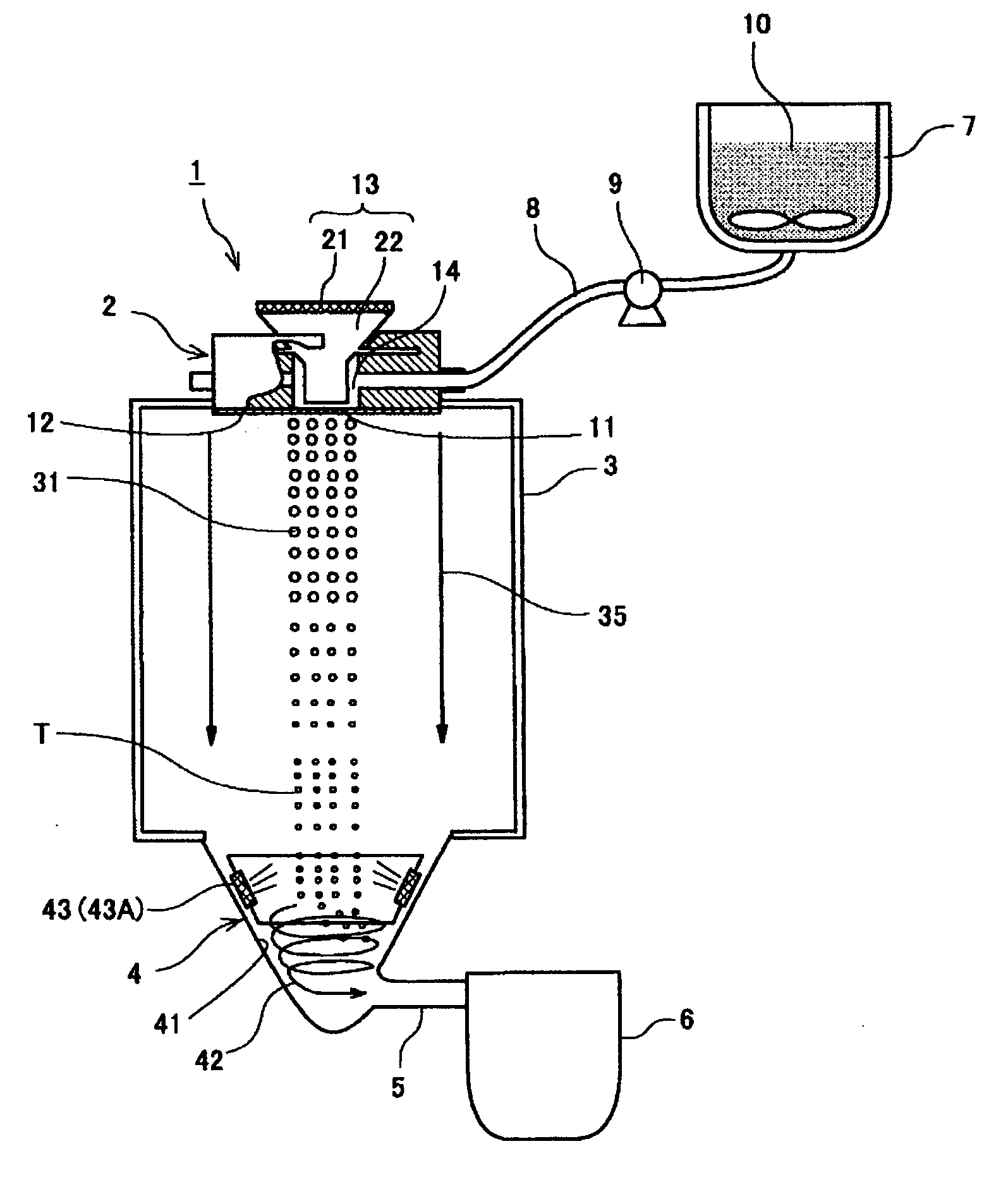
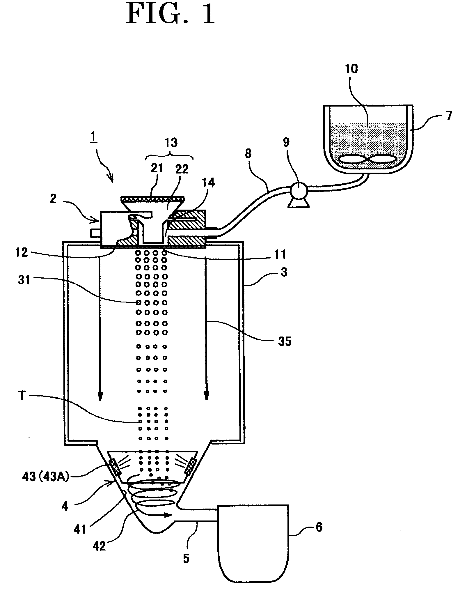
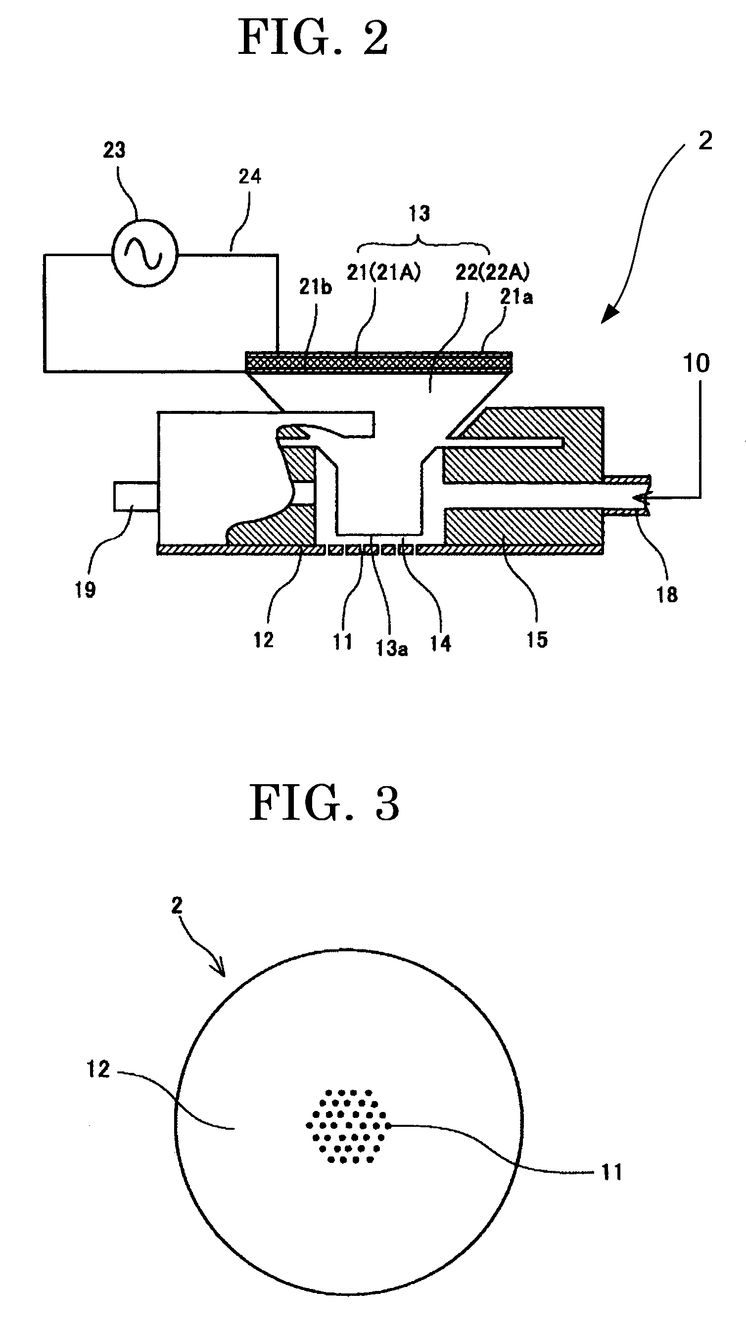
[0214]A “black toner c” and a developer were prepared in a similar manner to Example 1, except that the two-fluid spray nozzle was changed to a toner production apparatus as shown in FIG. 11 (a mechanically vibrating unit is formed in a circular ring shape so as to surround a thin film having a plurality of nozzles with a uniform diameter).

[0215]The obtained black toner c had an average circularity of 0.96 and a volume average particle diameter Dv of 5.1 μm; and the Dv / Dn ratio of the volume average particle diameter Dv to a number average particle diameter Dn measured was 1.09. Note that these values were measured in the same manner as in Example 1. The degree of irregularization of the shape of the black toner c was greater than those of Examples 1 and 2. Table 1 shows the measurement result.

[0216]It should be noted that the thin film used was prepared by electrocasting ejection holes (nozzles) each formed in a perfect circle and having a diameter of 8 μm, on a nickel plate of 8.0...


PUM

PropertyMeasurementUnit
Percent by massaaaaaaaaaa
Particle size distributionaaaaaaaaaa

Abstract

The present invention provides a toner containing at least two binder resins composed of at least a resin A and a resin B which are incompatible with each other, and a colorant, wherein the toner has an average circularity of 0.93 to 0.98 and is produced by atomizing a toner composition liquid in a vapor phase to form liquid droplets and solidifying the liquid droplets, and the toner composition liquid is prepared by dissolving or dispersing the at least two binder resins and the colorant in an organic solvent.

Description

TECHNICAL FIELD[0001]The present invention relates to a toner used in a developer for developing a latent electrostatic image in electrophotography, electrostatic recording, electrostatic printing and the like, and a method for producing a toner.BACKGROUND ART[0002]A toner used in electrophotography, electrostatic recording, electrostatic printing or the like is, for example, in a developing step, once adhered to an image bearing member such as a latent electrostatic image bearing member, on which surface a latent electrostatic image has been formed, is then transferred from the latent electrostatic image onto a transfer medium such as a transfer paper sheet in a transfer step, thereafter, is fixed on the surface of the paper sheet in a fixing step. At that time, since an untransferred toner which remains as residual toner on the latent electrostatic image bearing member with a latent image held on its surface, there is a need to remove the residual toner so as not to prevent the su...

Claims


Application Information

Patent Timeline
IPC IPC(8): G03G9/087
CPCG03G9/0804G03G9/0815G03G9/0819G03G9/0827G03G9/09G03G9/08753G03G9/08755G03G9/08795G03G9/08797G03G9/08711
Inventor WATANABE, YOHICHIROHSUZUKI, KAZUMIOHTANI, SHINJIHONDA, TAKAHIRONORIKANE, YOSHIHIRO
Owner RICOH KK
Learn More