Fluidic capillary chip for regulating drug flow rates of infusion pumps

a flow rate and pump technology, applied in the direction of flow monitors, lamination, medical devices, etc., can solve the problems of eroded delicate micro passageways, less than predictable working environment of the capillary chip of the prior art, and very delicate structure of the capillary chip

Inactive Publication Date: 2009-12-31
CODMAN NEURO SCI
View PDF12 Cites 43 Cited by
  • Summary
  • Abstract
  • Description
  • Claims
  • Application Information

AI Technical Summary

Benefits of technology

[0018]An erosion-resistant capillary chip, for use with in an infusion pump in accordance with the present invention that is made from a laminate of a silicon substrate and a glass plate. The silicon substrate includes a first surface that has a micro groove etched therein. The glass plate covers the micro groove so that a micro fluid conduit is created between the substrate and the glass plate. The glass plate includes an inlet bore that connects with the micro fluid conduit and the silicon substrate includes an outlet bore that connects with the

Problems solved by technology

The capillary chip of the prior art is a very delicate structure whose exacting dimensions must be maintained throughout the life of the infusion pump.
Unfortunately, the working environment of these chip capillaries is less than predictable and the drug solutions that continuously pass through them (albeit very slowly) come into direct contact with the relatively sensitive silicon oxide material.
This contact can lead to erosion of the delicate micro passageway located within the silicon struc

Method used


Image

  • Fluidic capillary chip for regulating drug flow rates of infusion pumps
  • Fluidic capillary chip for regulating drug flow rates of infusion pumps
  • Fluidic capillary chip for regulating drug flow rates of infusion pumps

Examples


Embodiment Construction

[0023]By way of overview and introduction, the present invention concerns improvements in the capillary chip assembly used in certain types of infusion pumps which allow such infusion pumps to operate more reliably, and for a greater period of time over pumps using conventional capillary chips, while introducing a safe-guard to the patient.

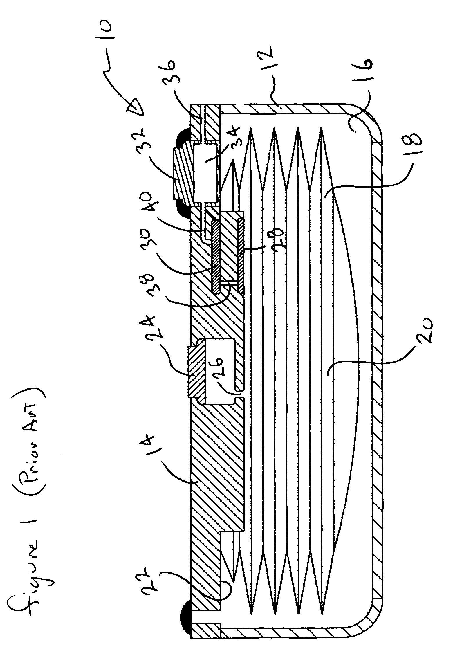
[0024]As a start, to help explain the present invention, a quick discussion of the structure and operation of a typical chip-capillary type infusion pump is in order. To this end, referring now to FIG. 1 (labeled PRIOR ART), a prior art infusion pump 10 is shown in section view, including a rigid housing 12 having a cover plate 14 and defining a gas-filled chamber 16. Located within the gas-filled chamber 16 is a flexible housing 18, which can expand and collapse as necessary within the rigid housing 12. This flexible housing 18 defines an infusate chamber 20 which is designed to hold the drug solution that is meant to be infused within the patien...


PUM

PropertyMeasurementUnit
Capillary waveaaaaaaaaaa
Flow rateaaaaaaaaaa
Corrosion resistanceaaaaaaaaaa

Abstract

An erosion-resistant capillary chip for use with in an infusion pump that is made from a silicon substrate having a first surface that includes a micro groove etched therein and a glass plate laminated to the first surface. The glass plate covers the micro groove so that a micro fluid conduit is created. The glass plate includes an inlet bore that connects with the micro fluid conduit and the silicon substrate includes an outlet bore that connects with the micro fluid conduit so that a drug solution entering the inlet bore from the infusion pump may pass through the micro fluid conduit at a restricted flow rate to the outlet bore and thereafter to a target site of a patient. The micro groove includes a passivation layer made from silicon nitride or silicon carbide that protects the micro groove against erosion from passing fluids having high basic or high acidic pH levels. A method for making the capillary chip is disclosed, as well as an infusion pump incorporating the improved capillary chip.

Description

BACKGROUND OF THE INVENTION[0001]1. Field of the Invention[0002]The present invention generally relates to implantable infusion pumps used to administer a controlled flow of drug into a patient, and more particularly, to improvements to micro capillary restrictor chips used to control the rate of flow in such devices.[0003]2. Description of the Related Art[0004]Medication infusion devices reached commercial and medical acceptance decades ago for administering a controlled amount of a drug into a patient over an extending period of time. Earlier units were typically secured to the patient outside the body, but eventually, the components and technology that make up these devices evolved to a size and shape that permitted them to be implanted and operate directly within the patient's body during the course of treatment.[0005]These implanted infusion pumps generally fall into two categories of operation, programmable devices and constant flow devices.[0006]Programmable Pumps[0007]Curren...

Claims


Application Information

Patent Timeline
IPC IPC(8): A61K9/22B32B37/02
CPCA61M5/141A61M5/14276A61M5/16813A61M5/16877A61M2205/0238F16K2099/0088A61M2205/0255A61M2205/0261F16K99/0001F16K99/0017F16K2099/0074A61M2205/0244
Inventor BORK, TORALFBIANCHI, FRANCOIS
Owner CODMAN NEURO SCI
Why Eureka
Try Eureka