Dual catalyst NOx reduction system for exhaust from lean burn internal combustion engines

a technology of internal combustion engine and nox reduction system, which is applied in the direction of machines/engines, separation processes, mechanical equipment, etc., can solve the problems of reduced nox emissions, limited commercial application of lean-operating engines, and reduced engine-out nox emissions, so as to eliminate about 95% of nox load

Active Publication Date: 2010-01-07
DELPHI TECH IP LTD
View PDF7 Cites 47 Cited by
  • Summary
  • Abstract
  • Description
  • Claims
  • Application Information

AI Technical Summary

Benefits of technology

[0019]A dual catalyst system in accordance with the present invention requires no precious metals and is capable of eliminating about 95% of the NOx load over a wide range of lean-burn operating temperatures.

Problems solved by technology

When an engine operates with a lean (excess oxygen) air / fuel ratio, the resultant combustion temperature is lower, leading to decreased engine-out NOx emissions; however, commercial application of lean-operating engines is limited due to lack of effective methods to remove NOx under a lean exhaust condition.
Reduction of NOx emissions from an exhaust feedstream containing excess oxygen is a challenge for vehicle manufacturers.
Use of urea as a reductant necessitates a urea storage and distribution infrastructure and an on-vehicle monitoring system for this secondary fluid, and may have potential problems in cold weather climates due to the relatively high freezing point (−12° C.) of the urea solution and deposits that can form in the exhaust at low temperatures.
Ion-exchanged base metal zeolite catalysts (e.g., Cu-ZSM5) have typically not been sufficiently active under typical vehicle operating conditions, and are susceptible to degradation by sulfur dioxide and water exposure.
However, as noted above, making NH3 in lean or oxidizing exhaust is difficult but possible with an appropriate catalyst.
However, such reductants typically are unavailable on-board a vehicle.

Method used


Image

  • Dual catalyst NOx reduction system for exhaust from lean burn internal combustion engines
  • Dual catalyst NOx reduction system for exhaust from lean burn internal combustion engines
  • Dual catalyst NOx reduction system for exhaust from lean burn internal combustion engines

Examples


Embodiment Construction

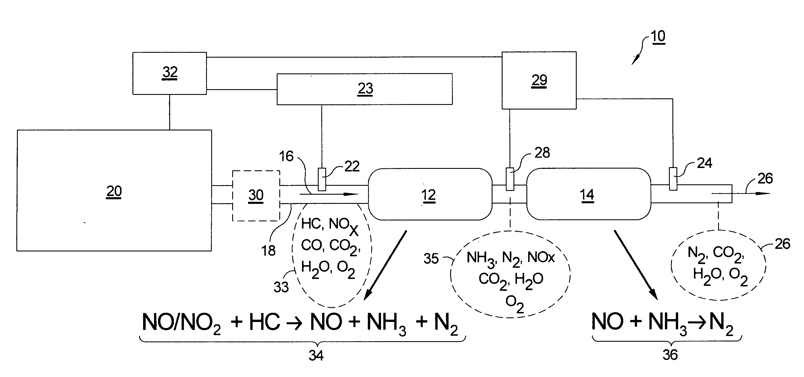
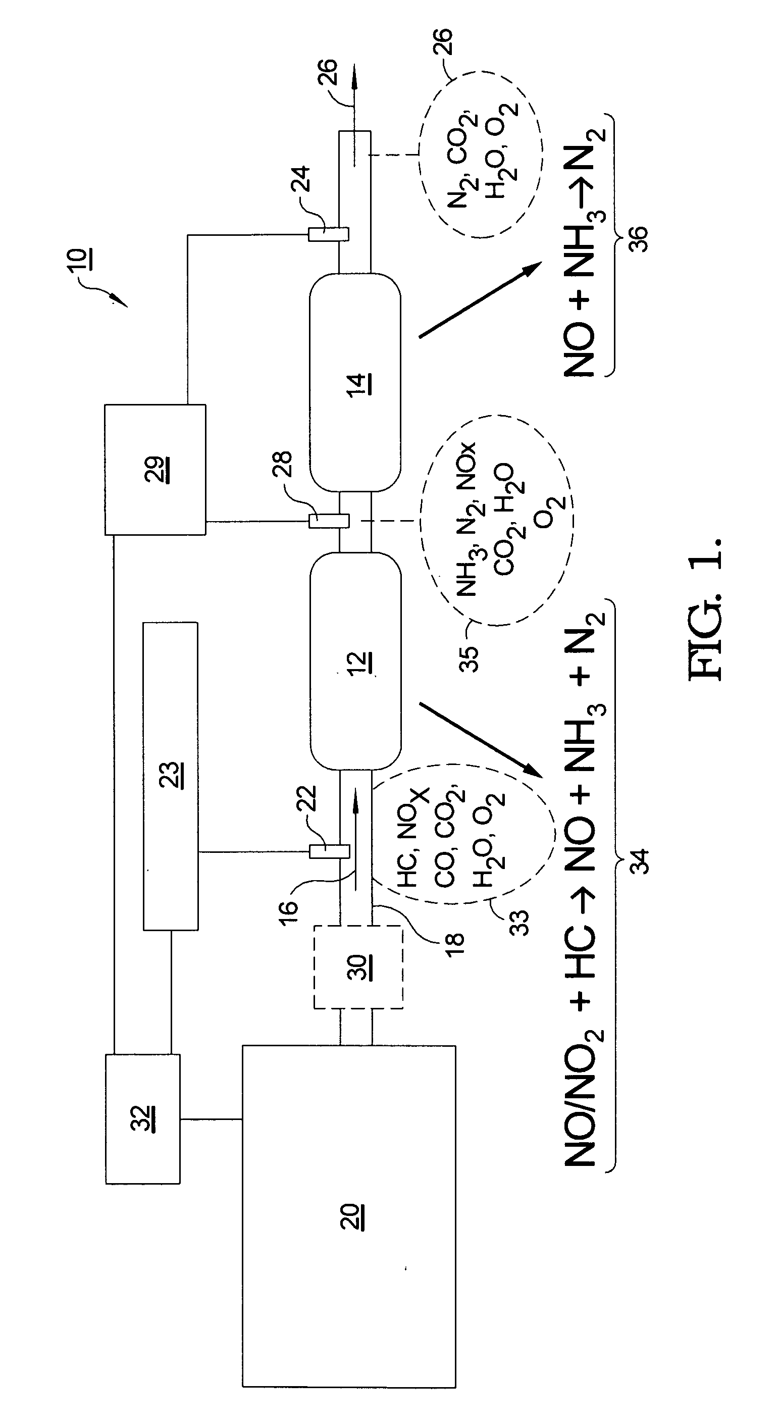
[0028]To meet the needs and competitive issues discussed above, an aftertreatment system in accordance with the present invention combines NOx species (NO and NO2), produced by combustion processes, with fuel HCs (e.g.,diesel fuel, gasoline, E85, or other fuels) and optionally H2 over a dual catalyst system to reduce NOx to nitrogen. (Diesel or “heavy” HCs as used herein means largely aliphatic hydrocarbons that are normally liquids at room temperature.) The source of the HCs can be from injection of reductants (e.g., fuel vapor) directly into the exhaust pathway, post injecting into the firing chamber in the combustion cycle which leaves larger HCs intact in the exhaust, or as the normal products of advanced premixed combustion modes. The object of the invention is to reduce tailpipe NOx levels to meet present and future emissions standards.

[0029]Referring to FIG. 1, a low cost dual-catalyst NOx reduction system 10 in accordance with the present invention comprises a first HC-NOx c...


PUM

PropertyMeasurementUnit
temperatureaaaaaaaaaa
freezing pointaaaaaaaaaa

Abstract

A method and apparatus for reducing the percentage of nitrogen dioxide and nitrogen monoxide in an exhaust gas stream of an internal combustion engine, comprising the steps of injecting a hydrocarbon compound and optionally hydrogen into the exhaust gas stream; passing the exhaust gas through a first catalyst for selective reduction of a portion of the nitrogen oxides to nitrogen, ammonia, and N-containing species; passing the exhaust gas through a second catalyst for selective reduction of a portion of the nitrogen oxides with ammonia to molecular nitrogen; sensing ammonia concentration in the exhaust gas stream after passage through either or both of the first and second catalysts; and controlling by a controller in a feedback loop the injecting to an amount of hydrocarbon that will produce a predetermined concentration of ammonia and nitrogen oxides at the sensor that will lead to high NOx conversion.

Description

TECHNICAL FIELD[0001]The present invention relates to means for reducing emissions from internal combustion engines; more particularly, to methods and apparatus for reducing engine emissions of nitrogen oxides (NOx); and most particularly, to a dual catalyst system for reducing NOx to N2 in lean-burn engines without the use of platinum group metals (PGM) in the catalysts.BACKGROUND OF THE INVENTION[0002]Internal combustion engines, and diesel engines in particular, are known to emit oxides of nitrogen under various operating conditions. Emissions limits promulgated by the US Federal government are stringent and are projected to become even more so. Accordingly, it is of great interest to engine and vehicle manufacturers to develop strategies for continuous removal of NOx from the exhaust streams of engines and to match those emission control strategies to the range of combustion modes possible in such engines.[0003]One such engine control strategy comprises operating an engine at an...

Claims


Application Information

Patent Timeline
Patent Type & Authority Applications(United States)
IPC IPC(8): F01N3/20
CPCB01D53/9418F01N2240/25B01D53/9495B01D2251/202B01D2251/208B01D2255/104B01D2255/20738B01D2255/20761B01D2255/2092B01D2255/50B01D2258/012B01D2258/014F01N3/2073F01N3/208F01N2560/021F01N2560/026F01N2560/14F01N2610/03F01N2610/04F01N2610/146Y02T10/24F01N13/0093F01N3/2066B01D53/9477Y02T10/12
Inventor FISHER, GALEN B.DIMAGGIO, CRAIG L.RAHMOELLER, KEN M.SELLNAU, MARK C.
Owner DELPHI TECH IP LTD
Why Eureka
Try Eureka