
Method for producing aluminum-alloy shaped product, aluminum-alloy shaped product and production system

a technology of aluminum alloy and production system, which is applied in the direction of heat treatment apparatus, machines/engines, furniture, etc., can solve the problems of difficult to reduce internal defects, difficult to reduce the weight of the piston, and inability to examine the mechanical characteristics of high-temperature cast products, etc., to achieve excellent mechanical strength, reduce the thickness of the piston, and achieve the effect of easy production of aluminum alloy

Inactive Publication Date: 2010-01-14
SHOWA DENKO KK
View PDF2 Cites 7 Cited by
  • Summary
  • Abstract
  • Description
  • Claims
  • Application Information

AI Technical Summary

Benefits of technology

[0027]According to the first invention described in (1), since the aluminum-alloy includes Si, Cu, Mg, and Ni, it is possible to obtain shaped products that have excellent high-temperature fatigue strength, forgeability, ductility, and toughness. Further, since the composition of Ni and Cu satisfies a relational expression of Ni(% by mass)≧[−0.68×Cu(% by mass)+4.2(% by mass)], it is possible to improve fatigue strength characteristics at higher temperature.
[0048]More specifically, for example, after aluminum-alloy shaped products are retained at a temperature of 350° C. for 100 hours, the fatigue strength thereof at a temperature of 350° C. becomes 33 MPa or more. These characteristics are, for example, characteristics required for a top surface portion of a piston of an internal combustion engine that comes in contact with a high temperature atmosphere. Accordingly, it is possible to further reduce the thickness of a piston of a conventional internal combustion engine by using the aluminum-alloy shaped product according to the present invention and to reduce the weight of a piston of an internal combustion engine. Further, it is possible to satisfy weight reduction required from the market, and realize to reduce fuel consumption of an internal combustion engine, and to improve output.

Problems solved by technology

However, in the case of such a cast product, difficulty is encountered in reducing internal defects generated during the course of casting, and excess material must be provided on the cast product so as to ensure safety design in terms of strength.
Therefore, when such a cast product is employed in an internal combustion engine piston, reducing the weight of the piston is difficult.
However, high-temperature mechanical characteristics of the cast product are not examined in Patent Document 1.

Method used


Image

  • Method for producing aluminum-alloy shaped product, aluminum-alloy shaped product and production system
  • Method for producing aluminum-alloy shaped product, aluminum-alloy shaped product and production system
  • Method for producing aluminum-alloy shaped product, aluminum-alloy shaped product and production system

Examples


examples

[0142]The present invention will be specifically described below by using examples. However, the present invention is not limited to these examples.

examples 1 to 16

[Manufacturing Conditions]

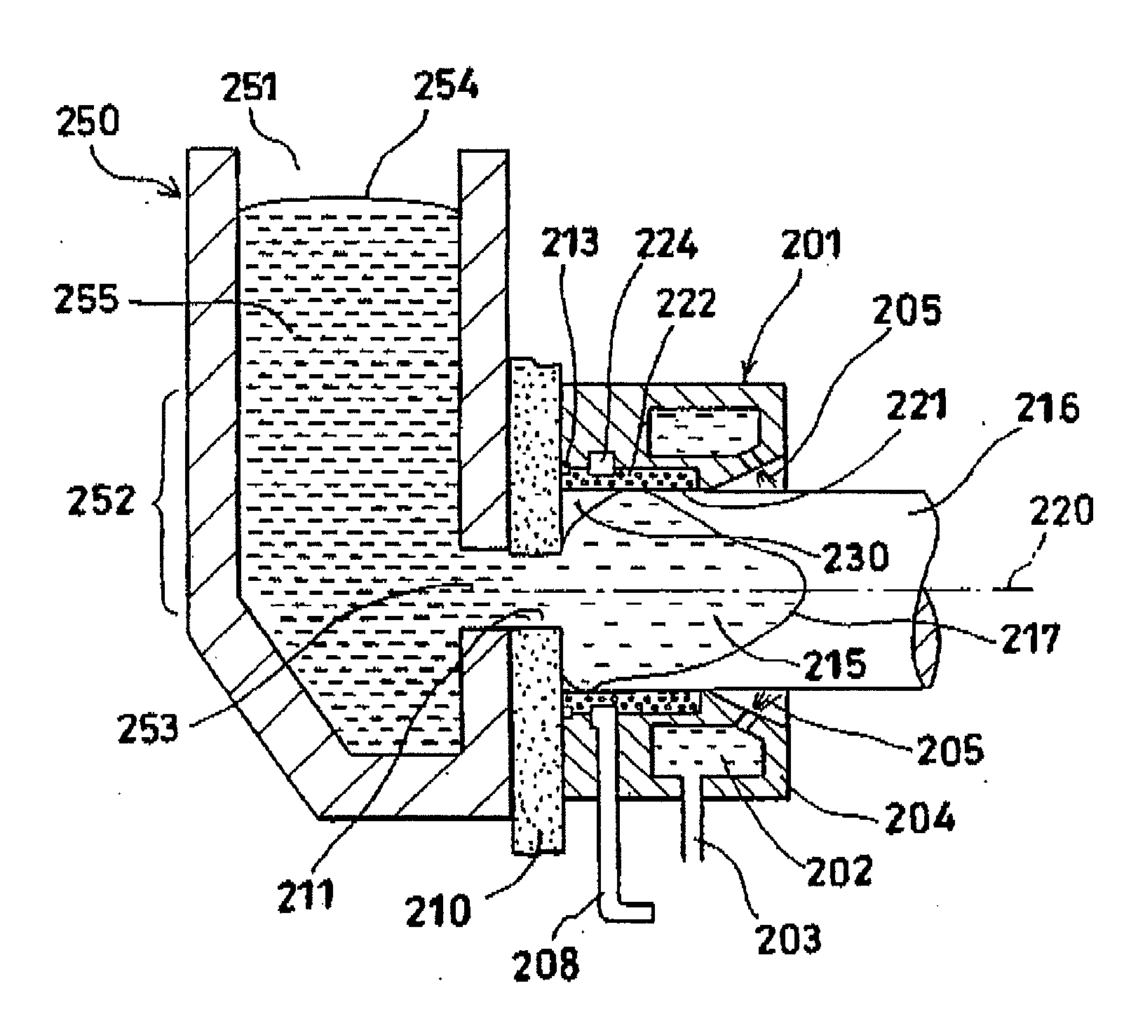
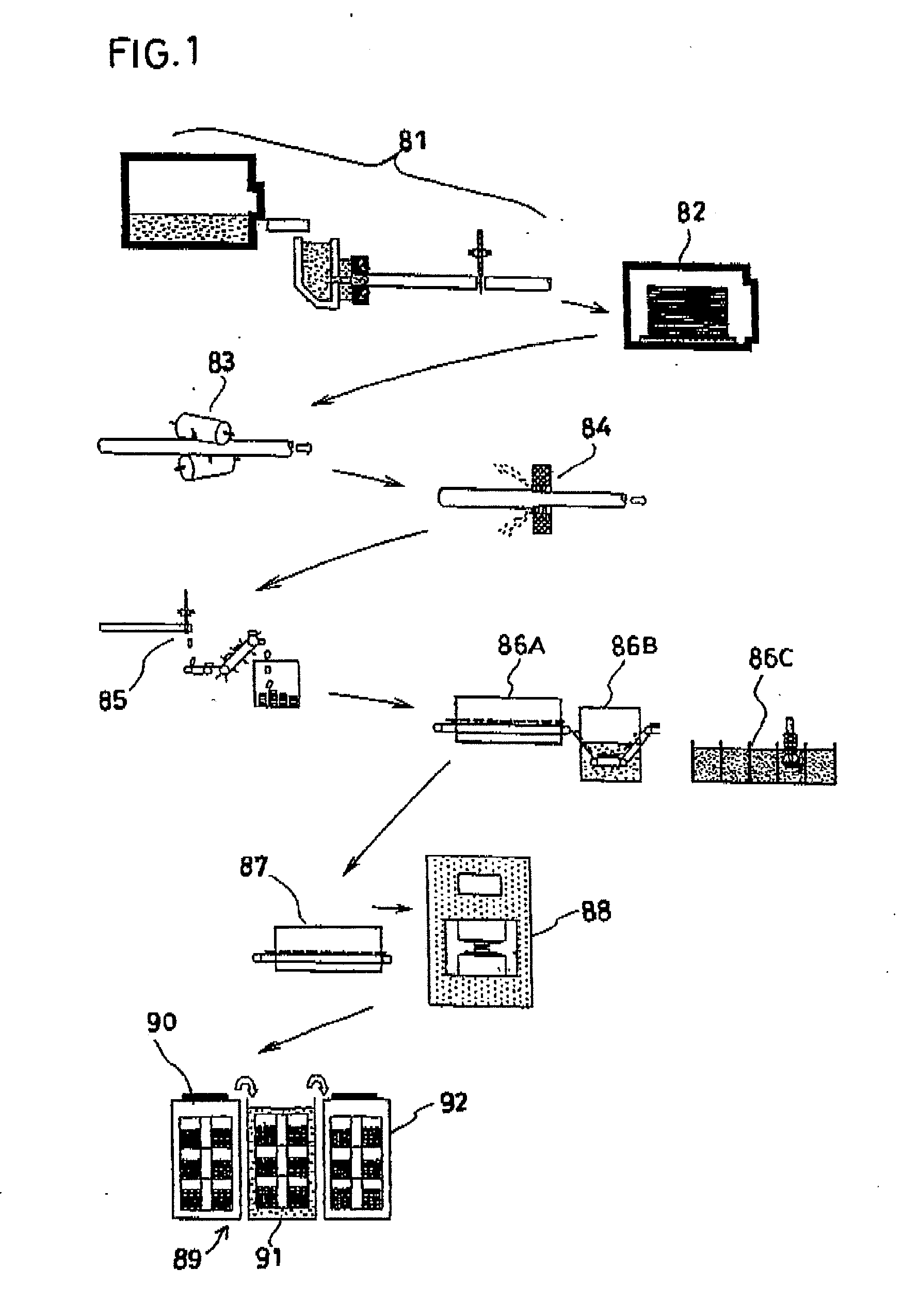
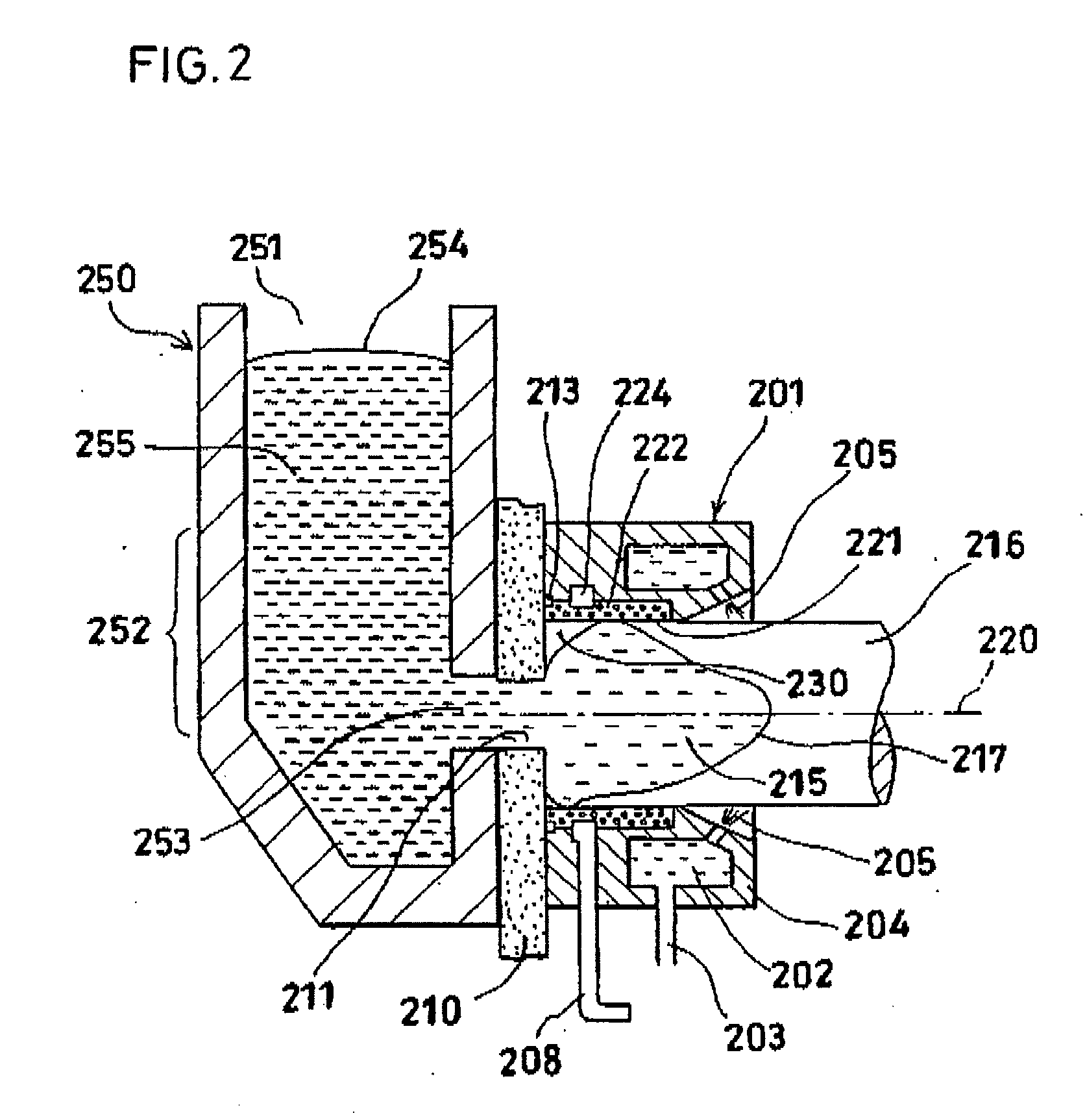
[0143]The aluminum-alloy shaped product of Examples 1 to 16 shown in Table 1 and Comparative Examples 1 to 10 shown in Table 2 were produced by a production system shown in FIG. 1.

TABLE 1TemperaturePercentPost-Fatigur Strength Stressof Homoge-reductionHeat(Unit: MPa)nizationduring theTreat-TemperatureTemperatureValueTreatmentcourse ofmentComposition of Aluminum-alloy (% by mass)ConditionConditionof(° C.)upsetting(T6, T5)SiFeCuMnMgNiTiPSr300° C.350° C.AAExample 137050%T610.50.252.7—0.953.8——0.01560455.64Example 237050%T610.50.252.7—0.953.8—0.015—59445.64Example 337050%T612.80.483.00.230.953.00.0750.018—59435.04Example 437050%T512.80.483.00.230.953.00.0750.018—62445.04Example 537050%T611.80.333.2—0.722.2—0.005—54394.38Example 637050%T612.80.253.8—0.951.8—0.018—53384.38Example 737050%T613.40.254.1—1.102.2—0.018—57434.99Example 837050%T613.40.614.10.321.212.2—0.010—58434.99Example 9not over 20050%T613.40.614.10.321.212.2—0.010—59444.99Example 1037050%T612.80.48...

examples 17 and 18

[Manufacturing Conditions]

[0162]Examples 17 and 18 and Comparative Examples 11 and 12, respectively, were produced under the composition and manufacturing conditions shown in Table 5 by the same method for production as Examples 1 to 16 and Comparative Examples 1 to 10.

[0163]Meanwhile, Comparative Example 13 was made of a powdery extruded-cast material, and was produced by the same method for production as Comparative Examples 11 and 12 except that Comparative Example 13 was not formed from a continuously cast round rod made of an aluminum-alloy and a homogenization treatment was not performed. All Examples 17 and 18 and Comparative Examples 11 to 13 were formed as the aluminum-alloy shaped product having the shape of a piston 1 that had a diameter of 80 mm and a top surface 10 having a thickness of 8 mm as shown in FIGS. 7A to 7C.

[Evaluation of Fatigue Strength]

[0164]The fatigue strength of each of Examples 17 and 18 and Comparative Examples 11 to 13 was evaluated by the following ...


PUM

PropertyMeasurementUnit
temperatureaaaaaaaaaa

Abstract

The present invention are to provide a method for producing an aluminum-alloy shaped product that exhibits high-temperature mechanical strength superior to that of a conventional aluminum-alloy forged product.The present invention provides a method for producing an aluminum-alloy shaped product, comprising a step of forging a continuously cast rod of aluminum-alloy serving as a forging material, in which the aluminum-alloy contains Si in an amount of 10.5 to 13.5 mass %, Cu in an amount of 2.5 to 6 mass %, Mg in an amount of 0.3 to 1.5 mass % and Ni in an amount of 0.8 to 4%, and satisfies a relational expression of “Ni(% bymass)≧(−0.68×Cu(% by mass)+4.2(% by mass)),and heat treatment and heating steps including a step of subjecting the forging material to pre-heat treatment (82), a step (87) of heating the forging material during a course of forging of the forging material and a step of subjecting an aluminum-alloy shaped product to post-heat treatment (89), said pre-heat treatment (82) including treatment of maintaining the forging material at a temperature of −10 to 480° C. for two to six hours.

Description

TECHNICAL FIELD[0001]The present invention relates to a method for producing an aluminum-alloy shaped product, which method includes a step of forging a continuously cast aluminum-alloy rod serving as a forging material, to an aluminum-alloy shaped product and to a production system for the shaped product.BACKGROUND ART[0002]In recent years, in vehicles such as four-wheel-drive automobiles and two-wheel-drive automobiles (hereinafter such a vehicle will be referred to simply as an “automobile”), attempts have been made to employ an aluminum-alloy forged product in an internal combustion engine piston in order to attain high performance or to cope with environmental regulations. This is because, when such an aluminum-alloy forged product is employed, the weight of driving parts (e.g., a piston) for an internal combustion engine can be reduced, leading to reduction of a load upon operation of the internal combustion engine, enhancement of output, or reduction of fuel consumption. Conv...

Claims


Application Information

Patent Timeline
Patent Type & Authority Applications(United States)
IPC IPC(8): C22F1/043C22C21/02C21D1/00
CPCB21J5/00B21K1/18B22D11/003B22D11/045B22D21/007B21J1/02C22F1/00C22F1/043F02F3/0084F05C2201/021C22C21/02B22D11/18
Inventor OKAMOTO, YASUO
Owner SHOWA DENKO KK
Learn More