Method for rapid generation of multiple investment cast parts such as turbine or compressor wheels

a technology of turbine or compressor wheels and investment casting, which is applied in the field of investment casting, can solve the problems of laborious and inaccurate techniques, difficult to form the sacrificial positive pattern necessary for investment casting, and excess capacity of conventionally employed aluminum alloys, so as to reduce the cost and lead time of parts, reduce the cost of parts, and eliminate the effect of capital expenditure for tooling

Active Publication Date: 2010-01-14
BORGWARNER INC
View PDF7 Cites 38 Cited by
  • Summary
  • Abstract
  • Description
  • Claims
  • Application Information

AI Technical Summary

Benefits of technology

[0052](B): a female shell, made of a refractory material, forming the outside surfaces of a plurality of sacrificial patterns and runners. This process removes capital expenditure for tooling, and reduces process time by up to 90%, depending upon the size of the part to be cast.
[0053]By removing several lengthy, time-dependant steps from the process the part cost and lead time are reduced.

Problems solved by technology

While aluminum had been a material of choice for compressor wheels due to low weight and low cost, the temperature at the blade tips, the stresses due to increased centrifugal forces at high RPM, and the accumulated damage due to the duty cycle exceed the capability of conventionally employed aluminum alloys.
Turbine wheels have a relatively simple shape as befits their function of being driven by exhaust gas flow, as well as historic limitations in both the structural aspect and the manufacturing process, and are today most commonly manufactured from an Inconel® super-alloy material using an investment casting process.
The complex shape makes it difficult to form the sacrificial positive pattern necessary for investment casting.
However, such a technique is labor intensive and not precise.
The basic process function is the same: produce a facsimile of the part which is then used to produce a female refractory shell.Repeatedly coating the sacrificial pattern with ceramic based refractory slurries, and drying each time, under controlled conditions, until a thick shell has been deposited on the outer features of the facsimile.This is an extremely time consuming operation.
Because the drying of said slurry must be controlled, to prevent unwanted shrinkage or cracking of the shell, this operation must take place in humidity and temperature controlled environment, which makes it both a time and capital intensive operation.
This operation often takes four to five days to execute.Shrinkage of the drying slurry is a complex subject, and a complicated process, which must be constantly monitored.
This practice is very labor intensive, slow, with risk to the surfaces of the sacrificial patterns, with testing and rejecting defective parts adding to the overall manufacturing cost of the individual parts.
Any handling damage to the very thin, fragile, wax or plastic blades becomes replicated in the cast metal part.
Any changes to the tooling must be logged and approved, which consumes resources.
This is actually a rather large cost item.
These alpha-phase inclusions may produce stress raisers which manifest themselves as failure sites particularly if they happen to lodge in a high stress area of the casting.
Unfortunately these alpha-phase impurities cannot be found superficially, by any non-destructive tests, and the existence of these impurities is often only discovered after they have initiated a failure site.
The automotive world is very cost conscious, often without the volumes to vindicate and support these high costs.
The process is very capital intensive on the front end, for the production of sacrificial patterns, time and space intensive in the middle stages and typical on the latter stages.
This teaching, as with patents in this art, is limited to production of single pieces.

Method used


Image

  • Method for rapid generation of multiple investment cast parts such as turbine or compressor wheels
  • Method for rapid generation of multiple investment cast parts such as turbine or compressor wheels
  • Method for rapid generation of multiple investment cast parts such as turbine or compressor wheels

Examples


second embodiment

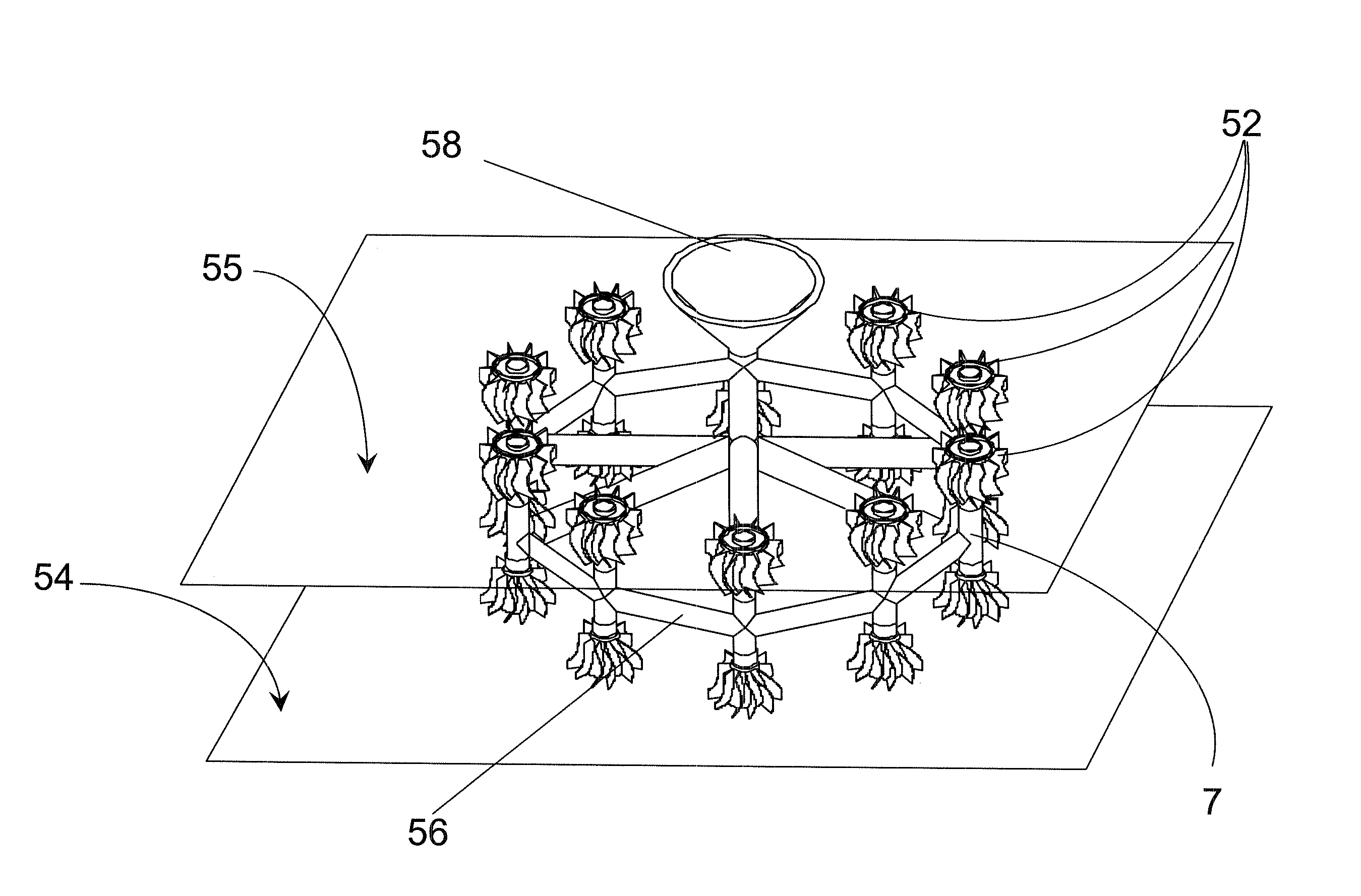
[0069]FIG. 6A illustrates only one turbine wheel of the “tree” of FIG. 5, showing in greater detail the sacrificial pattern (52), of FIG. 6A which is repeatedly dipped in a refractory slurry until the thin blade sections (8) become thick ceramic shells (12) as shown in FIG. 6B. During this process, the sprue (7) also acquires a ceramic shell with an outer surface (11) as well as an inner surface (10) surrounding the sacrificial core which will be removed to form the channel through which the molten material will travel to the wheel casting. This process produces the part depicted in FIG. 6B. This last operation, translating the image of FIG. A to the image of FIG. 6B is typical of the investment casting process. The end result of the above process becomes the end result of the invention, which is generated in a different and innovative manner.

[0070]A second embodiment of the invention, embodiment (B), will be explained by reference to FIG. 7. The methodology of a typical rapid proto...

first embodiment

[0075]In case (A), the invention: the present invention completely eliminates the capital cost of tooling, which can range from $20,000 to $150,000. In case (A), the patterns are made using technology which was formerly used only for rapid prototyping and these are merged with the historical process, in place of tooling. This reduces what was a 6 basic step process down to 5 basic steps.

[0076]In case (B), the second embodiment of the invention: the tooling, positive patterns and dipping and drying process are totally removed and replaced by a process in which the shell is produced as the first step in the foundry process. This takes what was a 6 basic step process down to 3 basic steps. The remaining 3 steps are eliminated.

[0077]The short term gains will be lowered capital costs, the longer terms gains will be lower capital tooling cost and no drying rooms being required.

[0078]Additional gains are realized in:[0079]Taking at least 4 days out of the 5 formerly required for drying. Be...


PUM

PropertyMeasurementUnit
lead timeaaaaaaaaaa
melting pointaaaaaaaaaa
exhaust energyaaaaaaaaaa

Abstract

The process for investment casting of complex shapes has historically had 6 basic steps in it. Depending upon the path taken, these discrete steps have been reduced to either 5 steps, or to 2 steps, discarding the unwanted steps. Instead of having to generate the shape of each sacrificial pattern, the process generates either(A) a male tree containing a plurality of sacrificial patterns, already on their runners, onto which a mold shell can be formed, or,(B) a female shell, made of a refractory material, and forming internally the outside surfaces of the plurality of patterns and runners.This process removes both capital expenditure for tooling and process time by up to 90%. By removing several lengthy, time-dependant steps from the process the part cost and lead time are reduced.

Description

FIELD OF THE INVENTION [0001]This invention is directed at improvements in the ancient art of investment casting, and particularly as it applies to manufacture of complex shapes such as turbocharger wheels, even titanium turbocharger wheels, as well as for parts which might be cast using the investment casting process but for geometry limitations in the part.DESCRIPTION OF THE RELATED ART[0002]Turbochargers are used on internal combustion engines to harness exhaust energy from the combustion system. Exhaust gas is used to drive a turbine which is mechanically connected to a compressor. The compressor is used to increase the density and pressure of the air entering the combustion chamber, which, when combined with the correspondingly increased amount of fuel, produces more power than would be generated using normal atmospheric air induction pressure. The design and function of turbochargers are described in detail in the prior art, for example, U.S. Pat. Nos. 4,705,463, 5,399,064, an...

Claims


Application Information

Patent Timeline
Patent Type & Authority Applications(United States)
IPC IPC(8): B22C9/00B22C7/00
CPCB22C7/02B29C67/0051B22C9/04B29C64/10B33Y50/00B33Y80/00Y02P10/25
Inventor ROBY, STEPHEN I.
Owner BORGWARNER INC
Why Eureka
Try Eureka