Detection method, detection apparatus, and sample cell and kit for detection

Inactive Publication Date: 2010-01-14
FUJIFILM CORP
View PDF9 Cites 12 Cited by
  • Summary
  • Abstract
  • Description
  • Claims
  • Application Information

AI Technical Summary

Benefits of technology

[0018]In view of the foregoing circumstances, it is an object of the present invention to provide a detection method and apparatus that can prevent variation in the intensities of signals, and that can efficiently utilize enhanced electric fields, and that can directly or indirectly detect fluorescence.
[0023]irradiating the sensor portion with excitation light to generate an enhanced optical field on the sensor portion; and
[0069]According to the detection method and apparatus of the present invention, an electrified fluorescent substance including a plurality of fluorescent dye molecules enclosed by a material that transmits fluorescence output from the plurality of fluorescent dye molecules is used as a fluorescent label of a fluorescent-label binding substance that binds to the sensor portion based on the amount of the detection target substance contained in a sample. Further, voltage is applied to the sample to attract the fluorescent substance to the surface of the sensor portion at which the optical field enhancement effect is high. Further, the fluorescent label contained in the fluorescent-label binding substance is excited, and the amount of light generated by the excitation is detected in a state in which the fluorescent substance is attracted to the surface of the sensor portion. Since the light is detected in such a manner, it is possible to efficiently use the optical field on the surface of the sensor portion at which the degree of enhancement of the optical field is high. Further, since it is possible to make the distances from the surface of the sensor portion to the fluorescent labels uniform (even), variation in the intensity of signals can be prevented. In other words, it is possible to detect stable signals at an excellent S / N ratio. Further, it is possible to accurately detect presence and / or the amount of the detection target substance.
[0070]When the sample cell for detection of the present invention or the kit for detection of the present invention is used, it is possible to easily carry out the detection method of the present invention. Further, it is possible to effectively use the enhanced optical field, and to prevent variation in the intensity of signals. Further, it is possible to accurately detect presence and / or the amount of the detection target substance.

Problems solved by technology

However, since both of the size and the charge of the detection target substance are small, the attraction effect by application of voltage is weaker than Brown motion of the detection target substance.
Therefore, it is difficult to efficiently attract the detection target substance to the surface of the sensor portion.
Therefore, there is a problem that when the distances from the surface to the fluorescent labels even slightly change, signals from the fluorescent labels become different from each other, and varied.

Method used


Image

  • Detection method, detection apparatus, and sample cell and kit  for detection
  • Detection method, detection apparatus, and sample cell and kit  for detection
  • Detection method, detection apparatus, and sample cell and kit  for detection

Examples


first embodiment

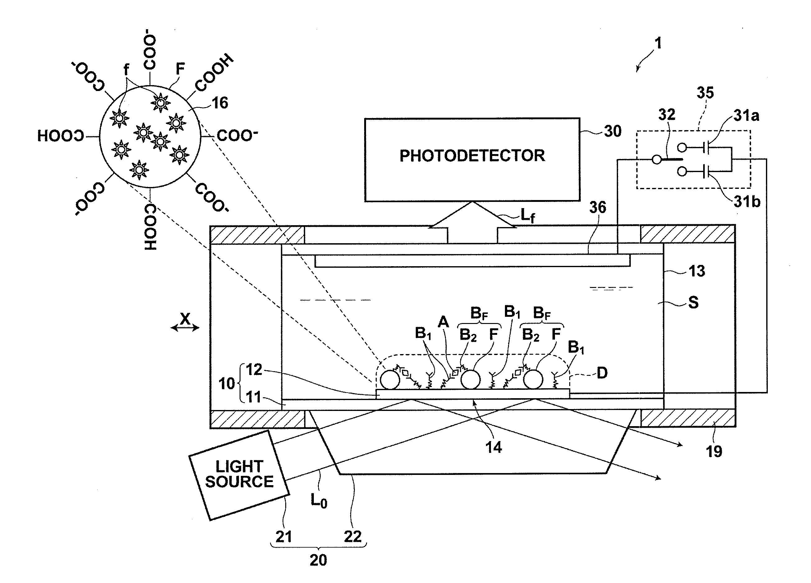
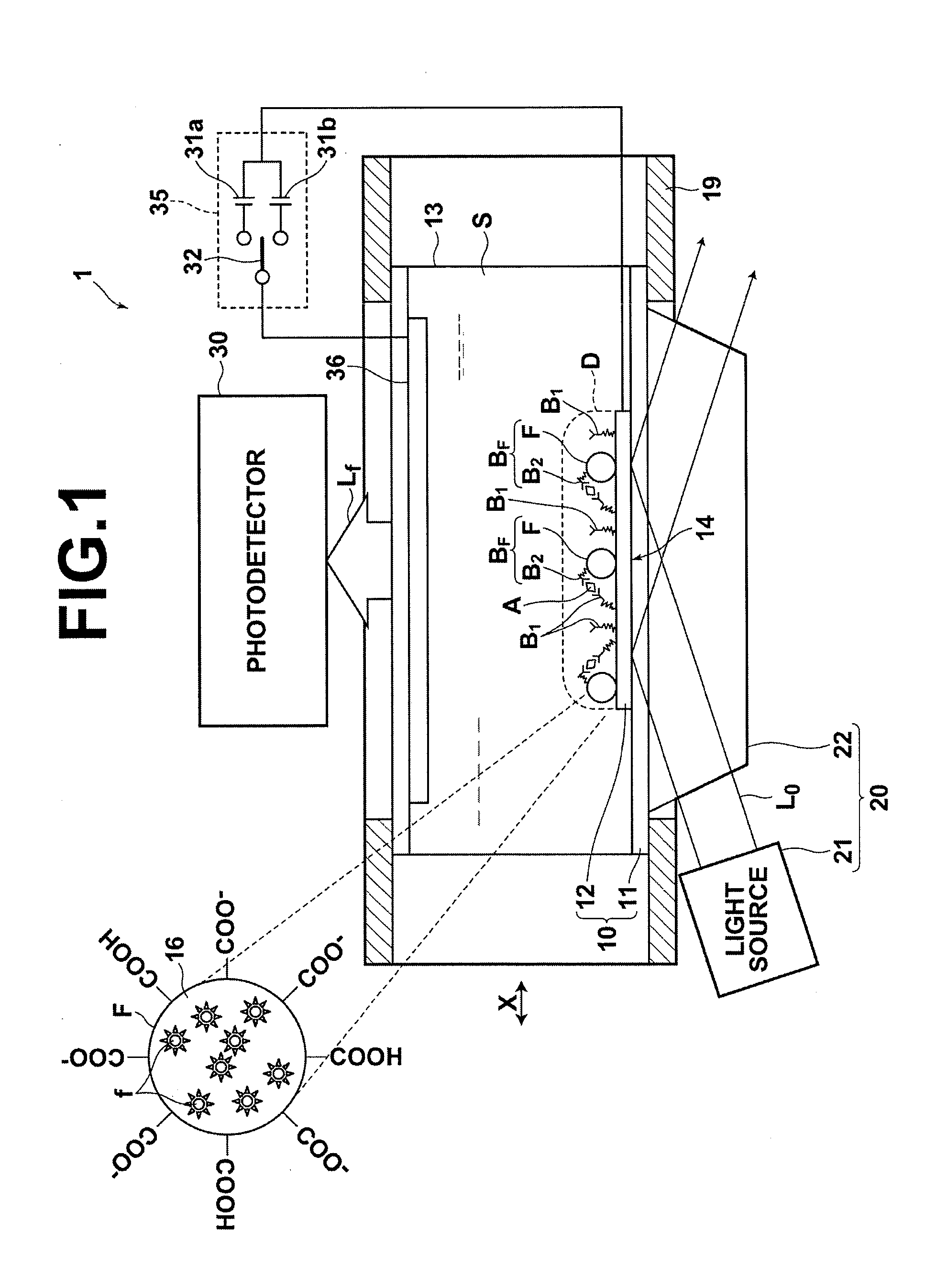
[0110]A detection method and apparatus according to a first embodiment will be described with reference to FIG. 1. FIG. 1 is a schematic diagram illustrating the structure of the whole detection apparatus of the first embodiment. The detection method and apparatus of this embodiment is a fluorescence detection method and apparatus that enhances an optical field by surface plasmon resonance, and detects fluorescence excited in the enhanced optical field.

[0111]In the fluorescence detection method of the present embodiment, a sensor chip 10 including a dielectric plate 11 and a sensor portion 14 that has at least a metal coating (metal film or thin-film or the like), as a metal layer 12, deposited in a predetermined area on a surface of the dielectric plate 11 is used. Further, a sample retaining unit 13 for retaining liquid sample S on the sensor chip 10 is provided. The sensor chip 10 and the sample retaining unit 13 constitute a box-form sample cell that can retain the liquid sample...

modification example

DESIGN MODIFICATION EXAMPLE OF FIRST EMBODIMENT

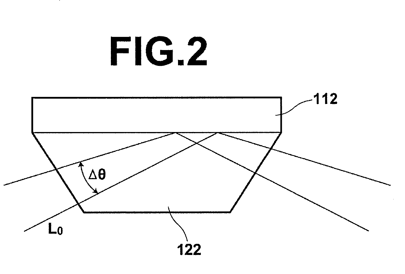
[0129]In each of the aforementioned examples, the excitation light L0 is collimated light that enters the interface at predetermined angle θ. Alternatively, the excitation light may be a fan beam (condensed light), as schematically illustrated in FIG. 2, which has angle width Δθ with respect to angle θ. When the excitation light is a fan beam, the excitation light enters the interface between the prism 122 and the metal film 112 on the prism 122 at an incident angle within the range of θ−Δθ / 2 to θ+Δθ / 2. When a resonance angle is present in the range of angles, it is possible to excite surface plasmons in the metal film 112. Further, the refractive index of the medium changes when the sample is supplied onto the metal film. In other words, the refractive index of the medium before supply of the sample and the refractive index of the medium after supply of the sample differ from each other. Therefore, the resonance angle at which surface ...

second embodiment

[0130]A detection method and apparatus according to a second embodiment will be described with reference to FIG. 3. FIG. 3 is a schematic diagram illustrating the structure of the whole detection apparatus of the second embodiment. The detection method and apparatus in this embodiment enhances an optical field by localized plasmon resonance, and detects fluorescence excited in the enhanced optical field. In the following descriptions, the same reference numerals will be assigned to elements corresponding to the elements in the first embodiment.

[0131]In a fluorescence detection apparatus 2 illustrated in FIG. 3, a sensor chip 10′ and an excitation light irradiation optical system 20′ differ from the elements of the fluorescence detection apparatus 1 of the first embodiment.

[0132]The sensor chip 10′ includes, as a metal layer 12′ provided on the dielectric plate 11, a metal fine structure body or a plurality of metal nanorods, which generate so-called localized plasmons by irradiation...


PUM


Abstract

A sensor chip including a sensor portion that has at least a metal layer deposited on a surface of a dielectric plate is used. A fluorescent-label binding-substance in an amount corresponding to the amount of a detection target substance in a liquid sample binds onto the sensor-portion. The amount of the detection target substance is detected based on the amount of light generated by excitation of a fluorescent label in the fluorescent-label binding substance. An electrified fluorescent substance containing a plurality of fluorescent dye molecules enclosed by a material that transmits fluorescence output from the plurality of fluorescent dye molecules is used as the fluorescent label. The electrified fluorescent substance is attracted to the sensor portion by applying voltage to the liquid sample in a state in which the fluorescent-label binding substance has bound to the sensor portion. In this state, the amount of the detection target substance is detected.

Description

BACKGROUND OF THE INVENTION[0001]1. Field of the Invention[0002]The present invention relates to a detection method, a detection apparatus, a sample cell for detection and a kit for detection to detect a substance to be detected (a detection target substance) in a sample.[0003]2. Description of the Related Art[0004]Conventionally, in the field of bio-measurement and the like, a fluorescence detection method is widely used as a highly accurate and easy measurement method. In the fluorescence detection method, a sample that is presumed to contain a detection target substance that outputs fluorescence by being excited by irradiation with light having a specific wavelength is irradiated with excitation light having the specific wavelength. At this time, fluorescence is detected to confirm the presence of the detection target substance. Further, when the detection target substance is not a phosphor (fluorescent substance), a substance that has been labeled with a fluorescent dye and that...

Claims


Application Information

Patent Timeline
IPC IPC(8): G01N21/64G01N21/05
CPCG01N2021/6439G01N21/648
Inventor OHTSUKA, HISASHIHORII, KAZUYOSHI
Owner FUJIFILM CORP
Why Eureka
Try Eureka