Multiple path length transmittance measuring device

a transmittance measuring device and multi-path technology, applied in instruments, liquid/fluent solid measurement, volume/mass flow by differential pressure, etc., can solve the problems of large errors in uvt/uva measurement, affecting the ability of uv light to transmit to the sensor, and very common fluctuation and dri

Active Publication Date: 2010-01-14
002134761 ONTARIO
View PDF0 Cites 17 Cited by
  • Summary
  • Abstract
  • Description
  • Claims
  • Application Information

AI Technical Summary

Benefits of technology

[0016]Embodiments of the apparatus disclosed herein efficiently ...

Problems solved by technology

There are two main challenges when designing UVT/UVA instrumentation.
The first challenge is due to the nature of UV light sources.
The most common UV light source is the mercury lamp, which has a tendency to drift and fluctuate causing significant errors in the UVT/UVA measurements.
Such fluctuation and drift is very common in UV lamps and is due primarily to changes in temperature and imperfections in the ballast and lamp, as well as the age of the lamp.
Another major difficulty when designing UVT/UVA instrumentation is due to fouling of the optical path by various types of matter in the water.
This deposition can significantly impair the UV light's ability to transmit to the sensor thereby causing significant errors.
The use of a blank sample for calibration, while potentially effective, causes various problems for both portable and online UVT/UVA measuring devices.
While the use of a blank sample as a reference for UVT/UVA calculations is acceptable in the lab it is not desirable in the field.
Carrying blank samples in the field can be cumbersome and can cause problems in harsh climates where temperature and freezing can affect the UVT/UVA of the blank sample.
For online UVT/UVA measuring devices, the use of a blank sample is especially problematic since these devices generally require a constant flow of test water through the flow cell through which the UVT/UVA is measured.
Clearly this is a time consuming process and prone to human error if performed by an operator.
Some devices attempt t...

Method used


Image

  • Multiple path length transmittance measuring device
  • Multiple path length transmittance measuring device
  • Multiple path length transmittance measuring device

Examples


Embodiment Construction

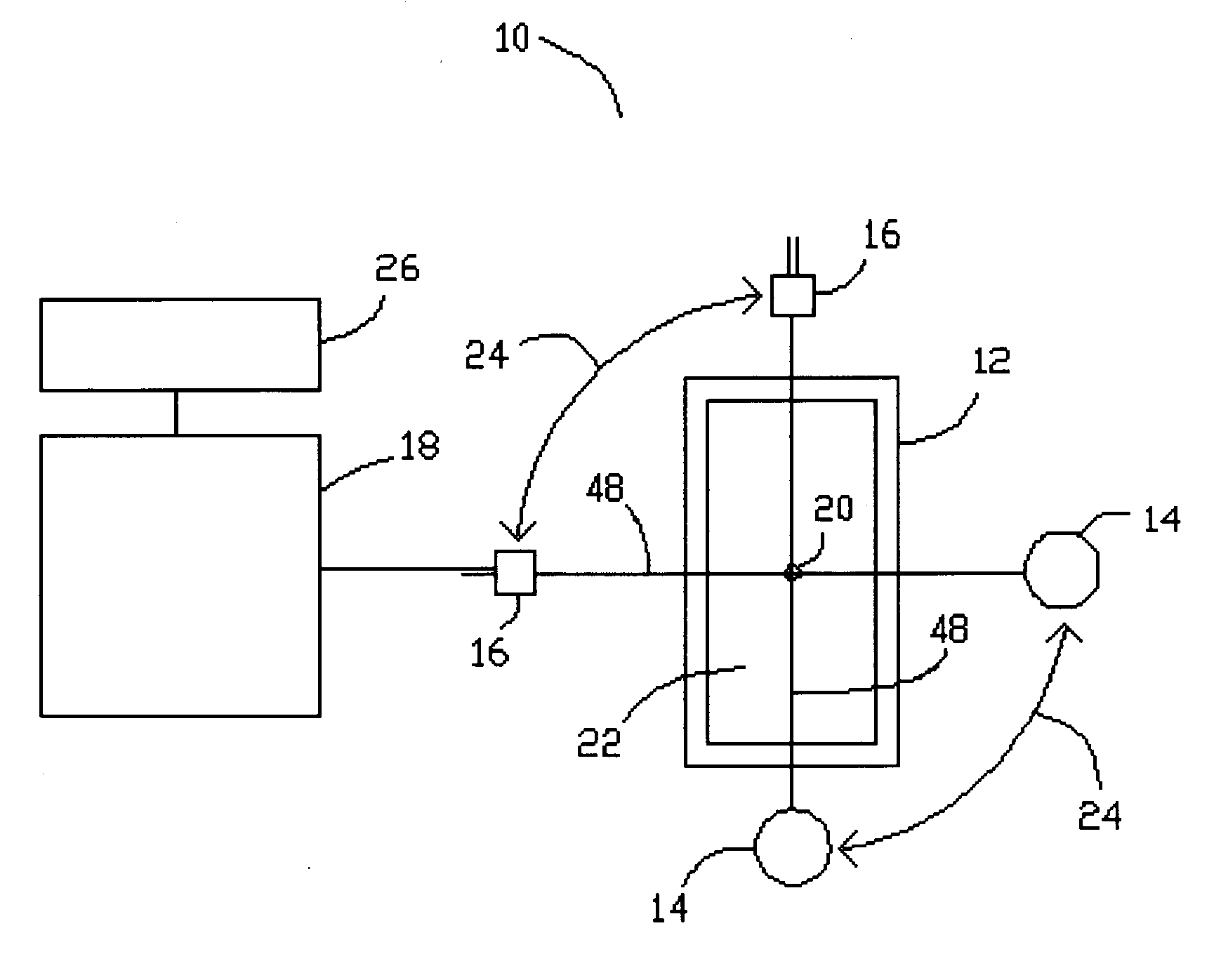
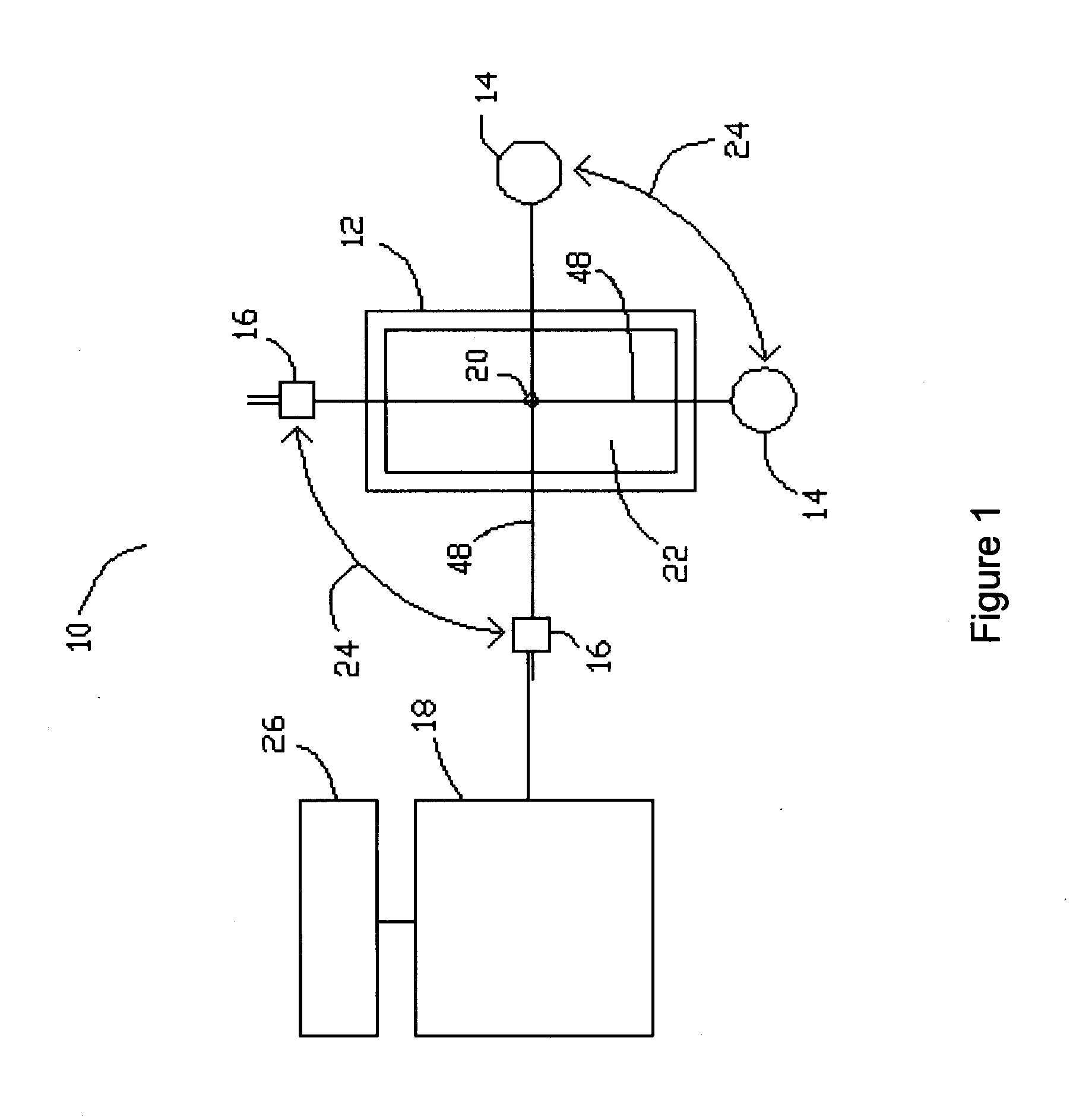
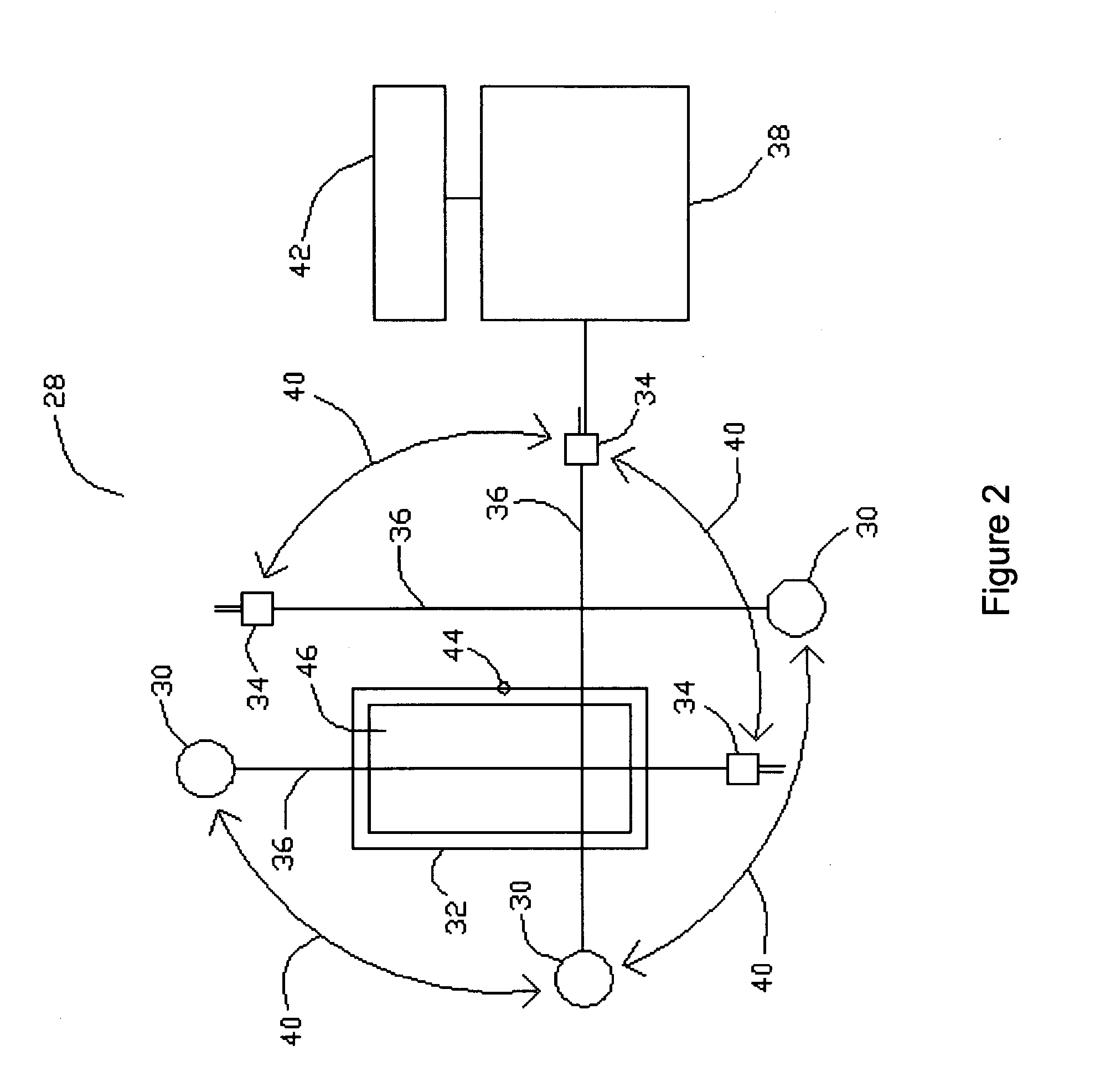
[0025]Generally speaking, the systems described herein are directed to an apparatus for measuring the transmittance of liquid samples to light using a multiple path length technique incorporating a moving measurement system. As required, embodiments of the present invention are disclosed herein. However, the disclosed embodiments are merely exemplary, and it should be understood that the invention may be embodied in many various and alternative forms. The Figures are not to scale and some features may be exaggerated or minimized to show details of particular elements while related elements may have been eliminated to prevent obscuring novel aspects. Therefore, specific structural and functional details disclosed herein are not to be interpreted as limiting but merely as a basis for the claims and as a representative basis for teaching one skilled in the art to variously employ the present invention. For purposes of teaching and not limitation, the illustrated embodiments are directe...


PUM


Abstract

A device to measure the amount of light able to transmit through a test liquid sample. A single lamp is used to illuminate a liquid sample cell containing the test water. A light detector is fixed relative to the lamp and is used to detect the amount of light from the lamp able to transmit through the liquid sample cell. The liquid sample cell is shaped in such a way as to provide at least two sets of opposed side walls that are able to transmit the light emitted from the lamp, where each set of opposed side walls defines a different path length through the liquid sample in the liquid sample cell. A rotation mechanism is used to provide relative rotation between the liquid sample cell and the lamp/light detector assembly. A microprocessor connected to the light detector calculates the light transmitted through at least two different path lengths through the liquid sample. Using these calculated transmittances the microprocessor then calculates the overall transmittance of the test water.

Description

CROSS REFERENCE TO RELATED U.S. PATENT APPLICATIONS[0001]This patent application relates to U.S. provisional patent application Ser. No. 60 / 818,968 filed on Jul. 7, 2006 entitled MULTIPLE PATH LENGTH TRANSMITTANCE MEASURING DEVICE, filed in English, which is incorporated herein in its entirety by reference.FIELD OF THE INVENTION[0002]The present invention is related to an apparatus for measuring water quality and particularly relates to several applications within the water and wastewater treatment industry.BACKGROUND OF THE INVENTION[0003]Rapid and reliable measurement of water quality is of major importance, particularly with respect to drinking water. Ultraviolet transmittance (UVT) is a water quality parameter that provides a measure of the amount of ultraviolet (UV) light able to transmit through a water sample. The ultraviolet absorbance (UVA) is a different representation of the measurement of UVT. UVA is mathematically related to UVT by the inverse log.[0004]The ultraviolet ...

Claims


Application Information

Patent Timeline
IPC IPC(8): G01N21/59G06F19/00
CPCG01N21/0303G01N21/05G01N21/33G01N21/59G01N21/534G01N2021/0378G01N21/532
Inventor GLOVER, JAMES ANDREW
Owner 002134761 ONTARIO
Why Eureka
Try Eureka