
Method of making an ion-switching device without a separate lithiation step

Inactive Publication Date: 2010-01-14
SAGE ELECTROCHROMICS
View PDF7 Cites 121 Cited by
  • Summary
  • Abstract
  • Description
  • Claims
  • Application Information

AI Technical Summary

Benefits of technology

[0023]Stacking this type of layers one above the other is standard in the art. What is now particularly surprising of the method is that the inventors found that when the metal-oxide of the electrode is superstoichiometric, a part of the lithium deposited during the electrolyte deposition step will enter the metal oxide lattice and be fixed while the remaining part of lithium can be reversibly extracted. By using a superstoichiometric metal oxide, the separate lithiation step turns out not to be necessary anymore resulting in a more efficient process.
[0033]Firstly, one can adapt the content of Li in the sputter target used to form the ion conductor layer. An increase in Li content will result in a faster ‘doping’ of the electrode, while a reduction in Li content will result in a slower ‘doping’ as less lithium atoms are bombarding the electrode during sputtering.
[0037]For anodically colouring materials like e.g. W—Ni—O the effect of lithiation is just the opposite. Initially the electrode layer is absorbing. Upon sputtering with LiPON, the lithium starts to intercalate and the layer becomes more and more transparent. The W—Ni—O layer will reach a maximum transmittance associated with a certain lithium content in the layer. Further lithium intercalation will reduce the transmittance. This point of maximum transmittance and the further decrease upon further decrease upon lithium intercalation can be used as a process control to stop the sputtering.
[0040]According a second aspect of the invention, a device, more in particularly an electrochromic device, is presented that at least comprises a stack of material made as per the method and variations to that method described above. Such a device comprises an electro conductive substrate on which a lithium activatable electrode comprising a metal oxide, more particularly a transition metal oxide, is coated. On top of the electrode a solid state electrolyte is sputter coated from a compound comprising lithium. Prior to coating the electrolyte, the metal oxide of the electrode contains more oxygen than prescribed by stoichiometry. The excess oxygen prevents the formation of a permanent coloration and makes a separate lithiation step superfluous.

Problems solved by technology

Wet chemical deposition techniques are not excluded but less preferred, as they frequently demand a further heat treatment and not always result in the optimal dense network or lattices for ion-switching purposes.

Method used


Image

  • Method of making an ion-switching device without a separate lithiation step
  • Method of making an ion-switching device without a separate lithiation step
  • Method of making an ion-switching device without a separate lithiation step

Examples


Embodiment Construction

.

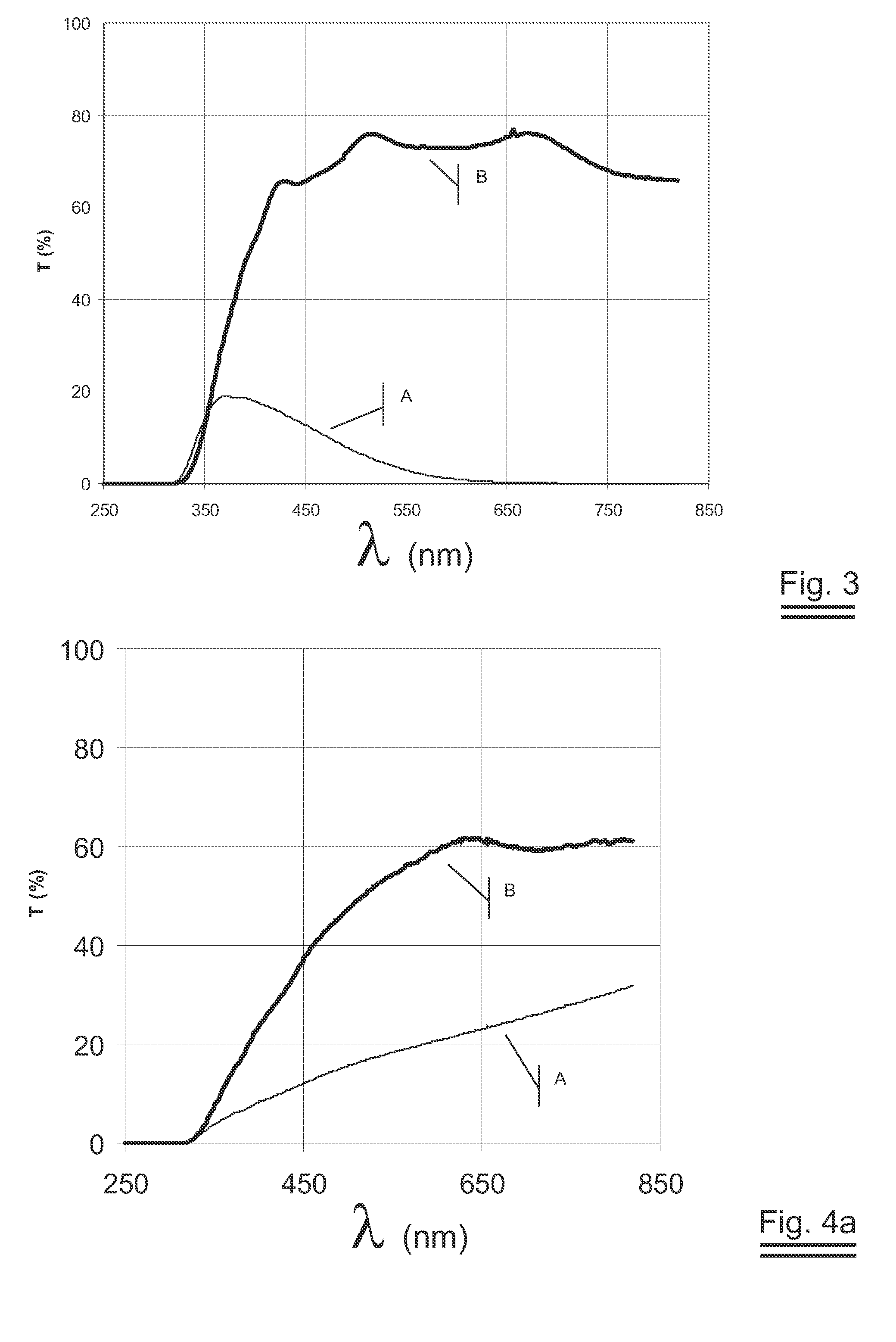
[0046]FIG. 3 shows the transmission results obtained on a second preferred embodiment EXAMPLE 2.

[0047]FIG. 4a shows the transmission results obtained on a third preferred embodiment EXAMPLE 3.

[0048]FIG. 4b shows the amount of lithium absorbed as function of the thickness on EXAMPLE 3.

[0049]FIG. 5 shows the in-situ monitored transmission of a fifth preferred embodiment EXAMPLE 5.

DESCRIPTION OF THE PREFERRED EMBODIMENTS OF THE INVENTION

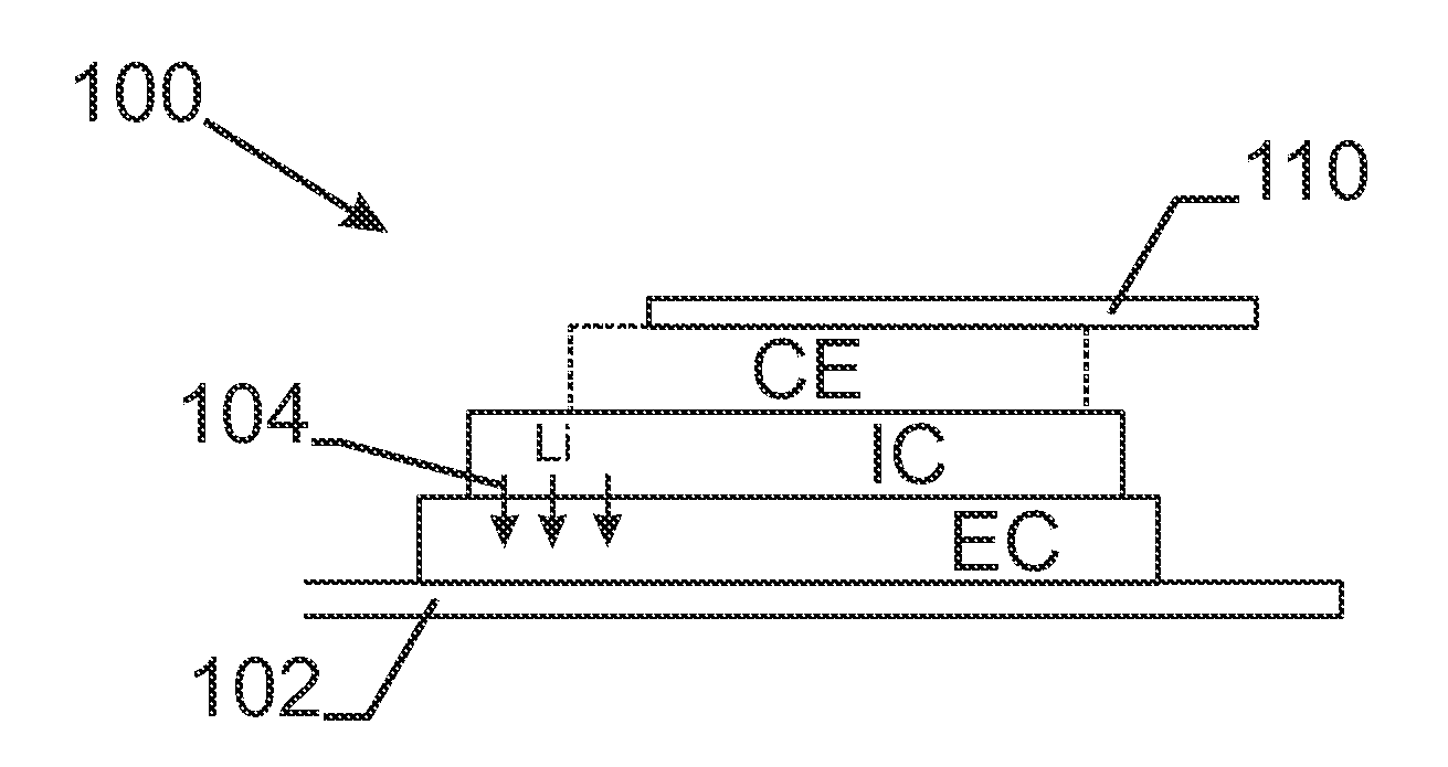
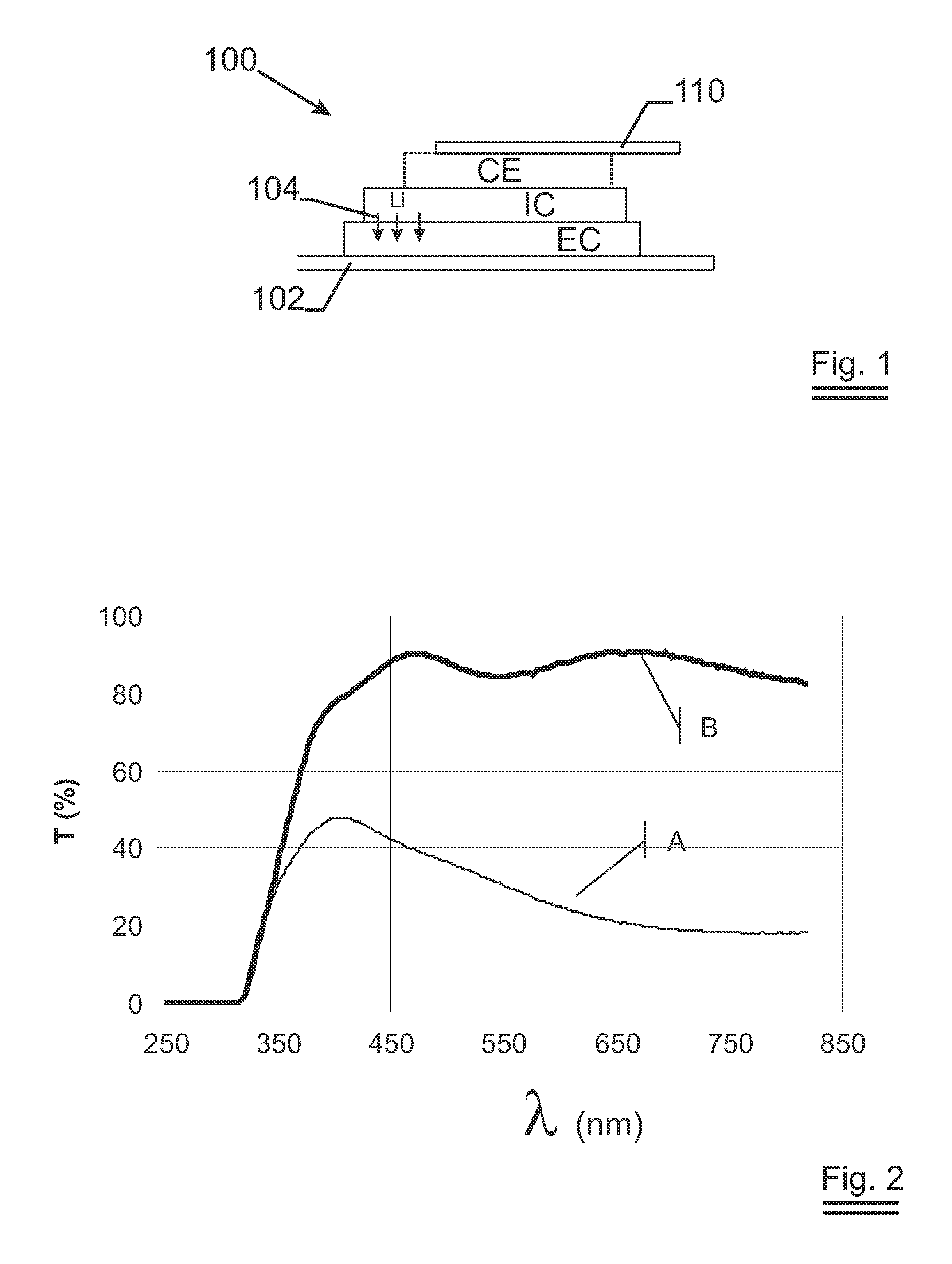
[0050]FIG. 1 describes a stack of a lithium ion switching device 100 in its most general form. There is the first electric contact 102 whereon an electrode EC is deposited. In the case of an electrochromic device, this electrode EC changes optical properties upon intercalation—shown with arrows 104—or de-intercalation of lithium. In the case of a battery, the electrode EC acts as a reservoir for Li having its lowest energy content when lithium is intercalated into the network. On top of the electrode EC, an ion conductor IC is sputtered. The ion conduc...


PUM

PropertyMeasurementUnit
electro conductiveaaaaaaaaaa
degree of optical transparencyaaaaaaaaaa
reflectivityaaaaaaaaaa

Abstract

In any manufacturing sequence for making a lithium ion-switching device, lithium has to be introduced at some stage into the device. An electrode inside the device is filled and depleted with lithium through an ion conductor at every use cycle of the device. Prior-art methods to introduce the lithium are: direct sputtering of lithium on the electrode, or electrochemically loading the electrode in an electrochemical cell, or indirectly loading the electrode after an ion conductor has been deposited on top of the electrode and still other methods. The inventive method disclosed makes such a separate lithiation step obsolete. The lithium is introduced at the same time as the ion-conductor is put on the electrode. This can be achieved by using an oxygen super-stoichiometric compound for the electrode.

Description

FIELD OF THE INVENTION[0001]The inventive process relates to lithium ion switching devices such as lithium based electrochromic appliances or lithium based secondary batteries.BACKGROUND OF THE INVENTION[0002]Lithium is the metal with the smallest atomic radius. This unique position in the periodic table of elements entails many advantageous properties. Its smallness allows lithium to intercalate easily into the network of many solids. Upon intercalation lithium easily loses its outer electron to the network thereby altering the electronic structure of the solid it invades. The altered electronic structure expresses itself in changes of e.g. electron conductivity or optical absorption. Over and above, in many networks the process of intercalation is reversible in that lithium can be extracted—or de-intercalated—out of the solid's network by application of e.g. an external electric field. This property is advantageously used in Li-ion batteries as they are nowadays widely used in hig...

Claims


Application Information

Patent Timeline
Patent Type & Authority Applications(United States)
IPC IPC(8): G02F1/155C23C14/46G02F1/1524
CPCY10S359/90G02F1/1523H01M4/0404H01M4/0426H01M4/483H01M10/0525H01M10/0562H01M10/0585G02F1/1524Y02E60/10Y02P70/50
Inventor WIDJAJA, EDYDELPORTE, GERDY
Owner SAGE ELECTROCHROMICS
Learn More