
Multiple channel locating

a multi-channel, multi-channel technology, applied in the direction of distance measurement, instruments, using reradiation, etc., can solve the problems of affecting the accuracy or resolution of stereo vision systems, affecting the accuracy of quantitative three-dimensional measurements, etc., to achieve high three-dimensional measurement speed and low cost

Active Publication Date: 2010-01-14
COGNEX CORP
View PDF3 Cites 318 Cited by
  • Summary
  • Abstract
  • Description
  • Claims
  • Application Information

AI Technical Summary

Benefits of technology

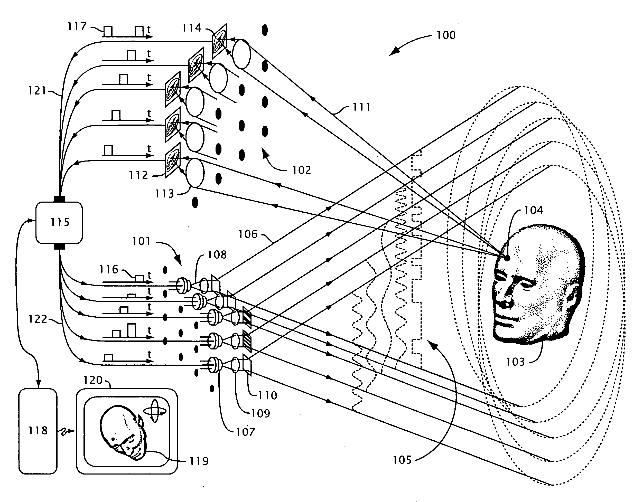
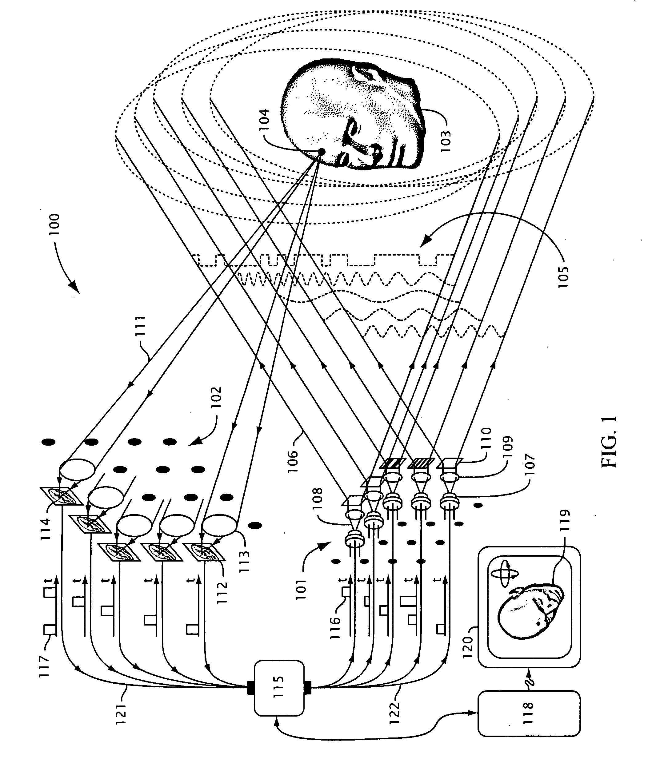
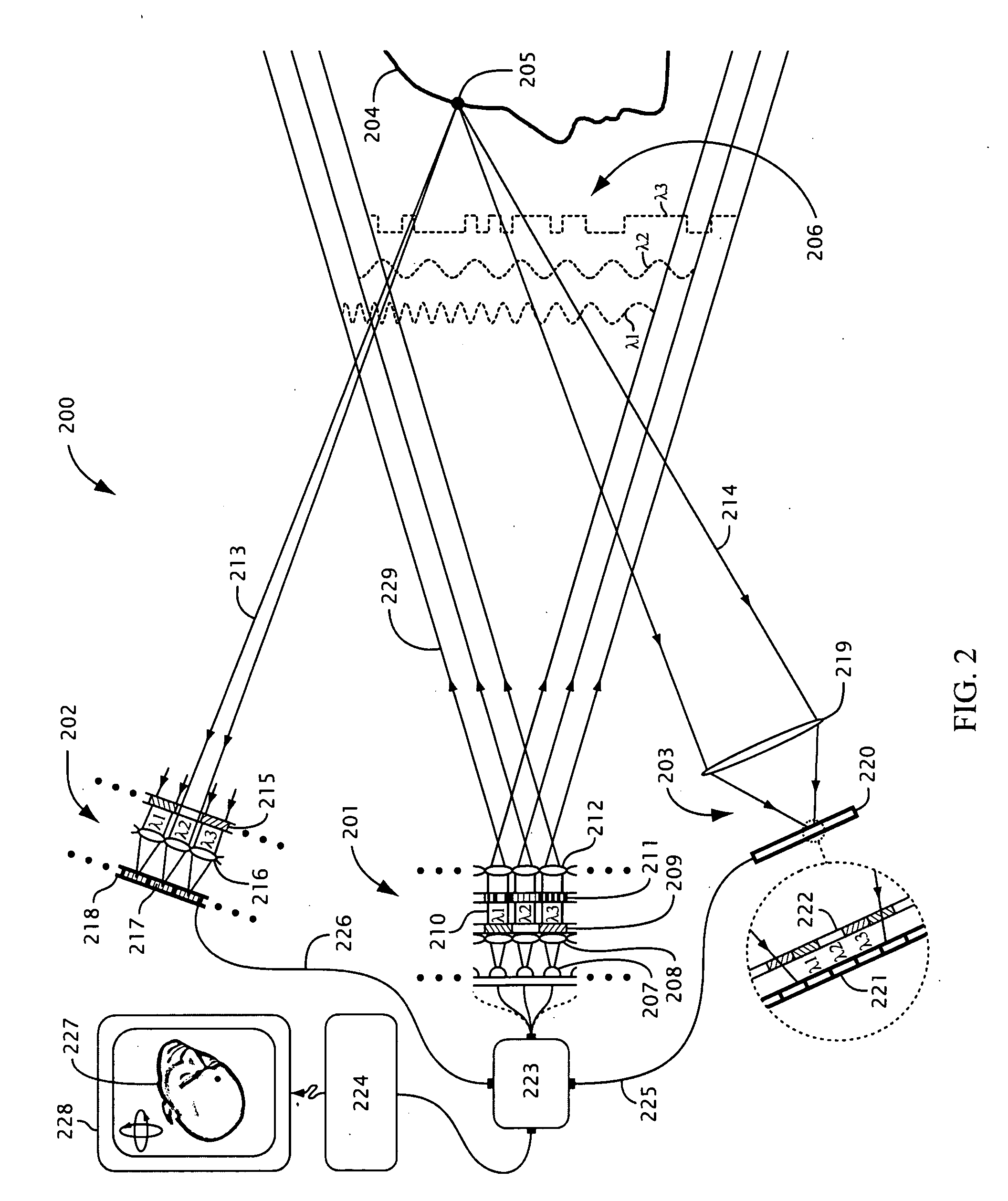
[0012]Certain embodiments of the inventions thus provide multiple channel locating tools and techniques that may address these needs. Some embodiments provide systems and methods for location-independent measurement of object surfaces and locations that may be robust to sources of error such as object discontinuities, surface properties including texture, reflectivity and coloration, lighting conditions, and noise propagation and may take advantage of multiple-channel pattern projection and imaging architectures. Some embodiments also provide multiple-channel locating systems that parallelize pattern projection and image acquisition using time, spectrum and / or polarization multiplexing and may attain higher three-dimensional measurement speeds than may be possible with conventional single-channel techniques that may rely on existing sequential pattern projection and image acquisition technology. Some embodiments may also enable three-dimensional surface shape measurement in high-speed single-shot events. Furthermore, some embodiments may provide compact, high-speed, low-power multiple-channel pattern projection and imaging systems that may be manufactured at low cost and may be integrated into mobile electronic devices for consumer applications and other three-dimensional surface shape measurement applications including robotics.

Problems solved by technology

For many objects and scenes, however, identifying correspondences may be a significant problem that may impede the use of stereo vision approaches for quantitative three-dimensional measurements.
Also, because the quality of the three-dimensional reconstruction depends on recognition of correspondences, stereo vision systems may not provide a guaranteed level of accuracy or resolution that is independent of the scene being imaged.
Robust encoding and decoding of the illumination angle for a wide range of objects and scenes is one of the foremost challenges in the field of three-dimensional surface measurement and profilometry.
Direct encoding techniques, however, may be very sensitive to optical and electronic noise, ambient lighting, detector linearity, as well as object texture, reflectivity and / or coloration.
Because temporal phase unwrapping approaches may need to project multiple patterns and / or acquire multiple images they may not be suitable for three-dimensional imaging of moving objects or stationary objects in a vibration-prone environment, since object motion relative to the illumination and / or the camera between the projection of successive patterns and acquisition of the corresponding images may corrupt the three-dimensional reconstruction.
Furthermore, temporal phase unwrapping techniques may not be suitable for capturing three-dimensional measurements of high-speed single-shot events such as impacts, explosions, and momentary facial expressions that may occur much faster than multiple frames can be acquired.
While direct encoding and pixel-dependent techniques may have the potential for high-speed surface profiling, they suffer from object-dependent, lighting-dependent and detector-dependent limitations as described above, and even the highest speed systems typically rely on pattern projection technology based on consumer electronics, such as liquid crystal and digital micromirror projectors, which may limit surface shape measurement speeds to approximately 60 frames per second (see S. Zhang, Optics and Lasers in Engineering, in press, doi:10.10.16 / j.optlaseng.2009.03.008, incorporated herein by reference).
One impediment for high-speed pixel-independent three-dimensional shape measurement has been the projection technology.
In these approaches, the sequential projection of multiple patterns may limit the speed at which a three-dimensional image can be acquired.
The speed of this technique, however, may be limited by the speed of acquiring multiple image frames.
Although the shift from projection-limited to imaging-limited shape measurement speed is significant, when used with typical commercial cameras, this technique may not offer a large speed advantage over systems based on high-speed pattern projectors.
However, the use of RGB pixels may be problematic for imaging of color objects.
Furthermore, the use of standard RGB cameras rather than a custom-designed optical multiplexing system may provide only a limited improvement in image acquisition speed, may lead to problems with crosstalk among the channels, and may suffer from detection sensitivity imbalance among the RGB pixels.
Moreover, because digital micromirror device (DMD) projectors typically used with RGB-multiplexed imagers generally utilize a single broadband source, a single modulating DMD device, and a spinning color filter wheel to produce patterns with different colors sequentially, the pattern projector may be a fundamentally a single-channel device rather than a parallel optical system and may limit the three-dimensional surface measurement speed regardless of parallelism in the imaging device.
While pixel-independent wide-field three-dimensional surface shape measurement systems may be more robust to variations in object structure and lighting conditions than stereo vision systems, they typically rely on bulky pattern projection systems using high-power illumination sources.

Method used


Image

  • Multiple channel locating
  • Multiple channel locating
  • Multiple channel locating

Examples


Embodiment Construction

[0035]This description provides example embodiments only, and is not intended to limit the scope, applicability, or configuration of the invention. Rather, the ensuing description of the embodiments will provide those skilled in the art with an enabling description for implementing embodiments of the invention. Various changes may be made in the function and arrangement of elements without departing from the spirit and scope of the invention.

[0036]Thus, various embodiments may omit, substitute, or add various procedures or components as appropriate. For instance, it should be appreciated that in alternative embodiments, the methods may be performed in an order different from that described, and that various steps may be added, omitted, or combined. Also, features described with respect to certain embodiments may be combined in various other embodiments. Different aspects and elements of the embodiments may be combined in a similar manner.

[0037]It should also be appreciated that the ...


PUM


Abstract

Methods, systems, and apparatuses are provided for estimating a location on an object in a three-dimensional scene. Multiple radiation patterns are produced by spatially modulating each of multiple first radiations with a distinct combination of one or more modulating structures, each first radiation having at least one of a distinct radiation path, a distinct source, a distinct source spectrum, or a distinct source polarization with respect to the other first radiations. The location on the object is illuminated with a portion of each of two or more of the radiation patterns, the location producing multiple object radiations, each object radiation produced in response to one of the multiple radiation patterns. Multiple measured values are produced by detecting the object radiations from the location on the object due to each pattern separately using one or more detector elements. The location on the object is estimated based on the multiple measured values.

Description

CROSS-REFERENCES TO RELATED APPLICATIONS[0001]This application is a non-provisional of, and claims the benefit of, U.S. Provisional Patent Application Ser. No. 61 / 079,128 entitled “Single-Shot Range Imaging System and Method and Non-Periodic Radiation Pattern Generation System and Method,” filed Jul. 8, 2008, the entire disclosure of which is incorporated herein by reference for all purposes.BACKGROUND[0002]The present invention relates to apparatuses, systems, and methods for determining the three-dimensional location of one or more locations on the surface of an object. More specifically, the present invention relates to methods, systems, and apparatuses involving non-contact three-dimensional location estimating using multiple-channel pattern projection and multiple-channel image recording architectures.[0003]Measurement of three-dimensional object surfaces may be needed for a number of applications, including quality insurance for manufacturing, reverse engineering, as-built doc...

Claims


Application Information

Patent Timeline
Patent Type & Authority Applications(United States)
IPC IPC(8): G06K9/52G01S7/486G01S17/89
CPCG01B11/2518G01B11/2527G01B11/2536G01S7/4815G01S7/4818G01B11/005G01S7/486G01S7/499G01S17/48G01S17/89G01C3/08G01S7/484
Inventor FELDKHUN, DANIELBRAKER, BENJAMINMOORE, ERIC DANIEL
Owner COGNEX CORP
Learn More