Highly Dispersed Metal Catalysts

a metal catalyst, high-dispersion technology, applied in physical/chemical process catalysts, organic compound/hydride/coordination complex catalysts, separation processes, etc., can solve the problems of insufficient interaction between gold particles, catalyst life, and inability to commercialize au-based catalysts, etc., to achieve high efficiency and stable

Inactive Publication Date: 2010-01-14
AGENCY FOR SCI TECH & RES
View PDF14 Cites 47 Cited by
  • Summary
  • Abstract
  • Description
  • Claims
  • Application Information

AI Technical Summary

Benefits of technology

[0026]The catalysts prepared in the present invention have the advantages of high activity, for example, in one aspect, the catalyst has a fast reaction rate at low temperatures and good stability over an extended period of use. The catalysts prepared according to the methods of the present invention also have a low content of halide anion residue, which minimizes the poisoning of the catalyst as well as having high stability against calcinations.

Problems solved by technology
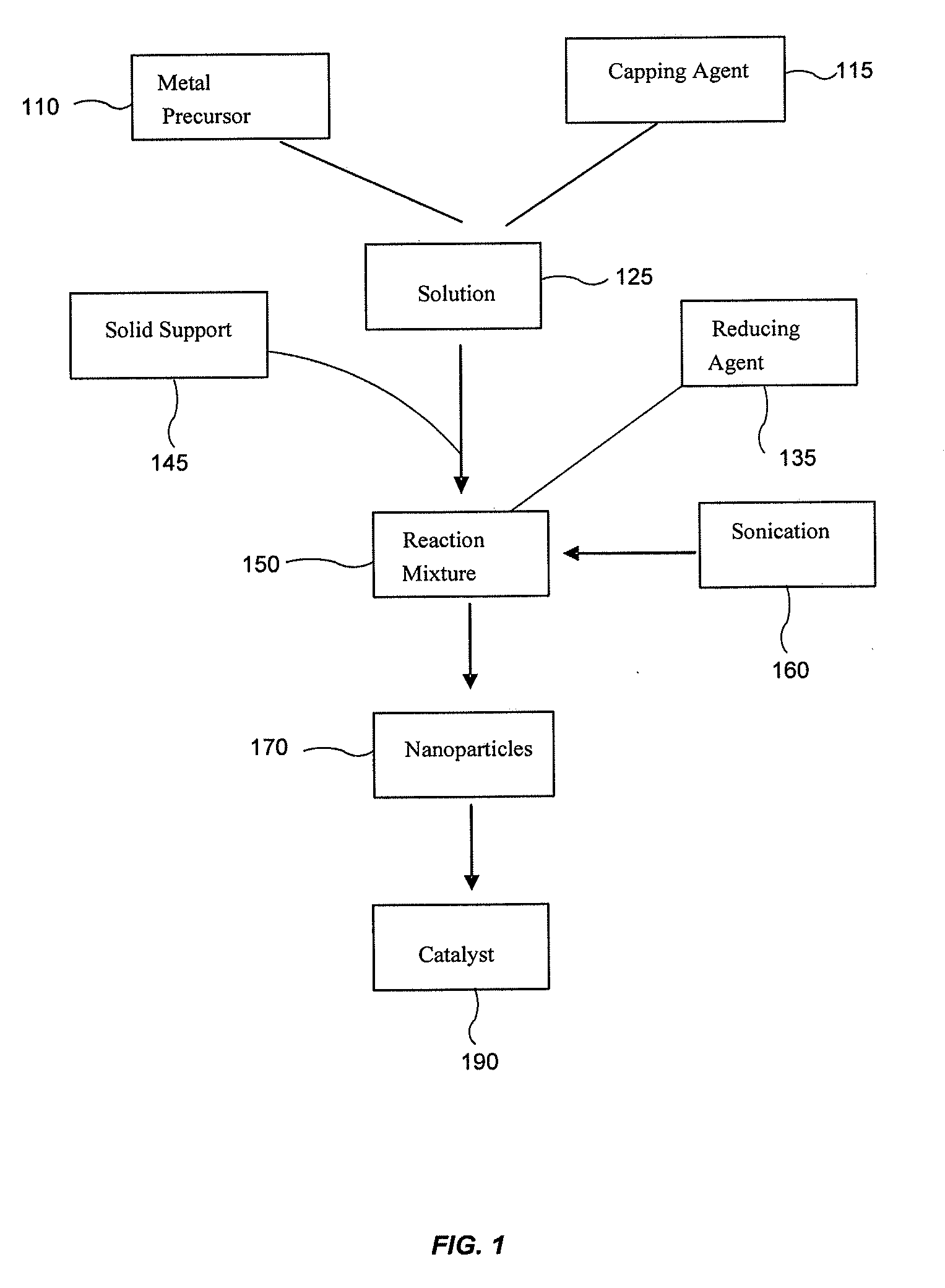
Despite the activity in oxidizing carbon monoxide, Au-based catalysts cannot be commercialized due to its short lifetime and the catalytic efficiency of the catalyst.
The factors affecting the lifetime of the catalyst include an insufficient interaction between gold particles and the support.
Impregnation and incipient wetness techniques provide poor control on Au particle size with a limited Au loading.
The complete removal of chloride anion, an inhibitor to the catalyst, is also proven to be difficult (see, Ponec, V. et al., Catalysis by metals and alloys, Amsterdam 1996; Galvagno, S. et al., J. Catal., 1978, 55, 178; Cant, N. W., et al.
However, the method has the limitation of consuming large quantities of water, and the reaction is carried out with heating at a high temperature (≧80° C.) from one to several hours.
Since the particles are typically produced through extensive heating at an elevated temperature, solid supports materials are limited under the high temperature process.
Other methods including cationic adsorption or use of organogold complex are more expensive compared with the above methods.
Sputtering and laser ablation methods can provide good control on Au particle size, but the apparatus can be quite expensive and the scale-up of the production is difficult (See, Fan, L. et al.

Method used


Image

  • Highly Dispersed Metal Catalysts
  • Highly Dispersed Metal Catalysts
  • Highly Dispersed Metal Catalysts

Examples


example 1

Preparation of Au Catalyst

[0067]The Au catalysts were prepared using HAuCl4 as a precursor, NaBH4 as a reduction agent and amino acid as a capping agent. During the reduction period, sonication was applied (e.g. 20 seconds). Next, the catalyst was separated using centrifuge and washed with deionized water. The advantages of our method are low reaction temperature and suitability for various catalyst supports. The catalytic activities of the catalysts for CO oxidation in air and in the presence of H2, respectively, are comparable to the best prior art results.

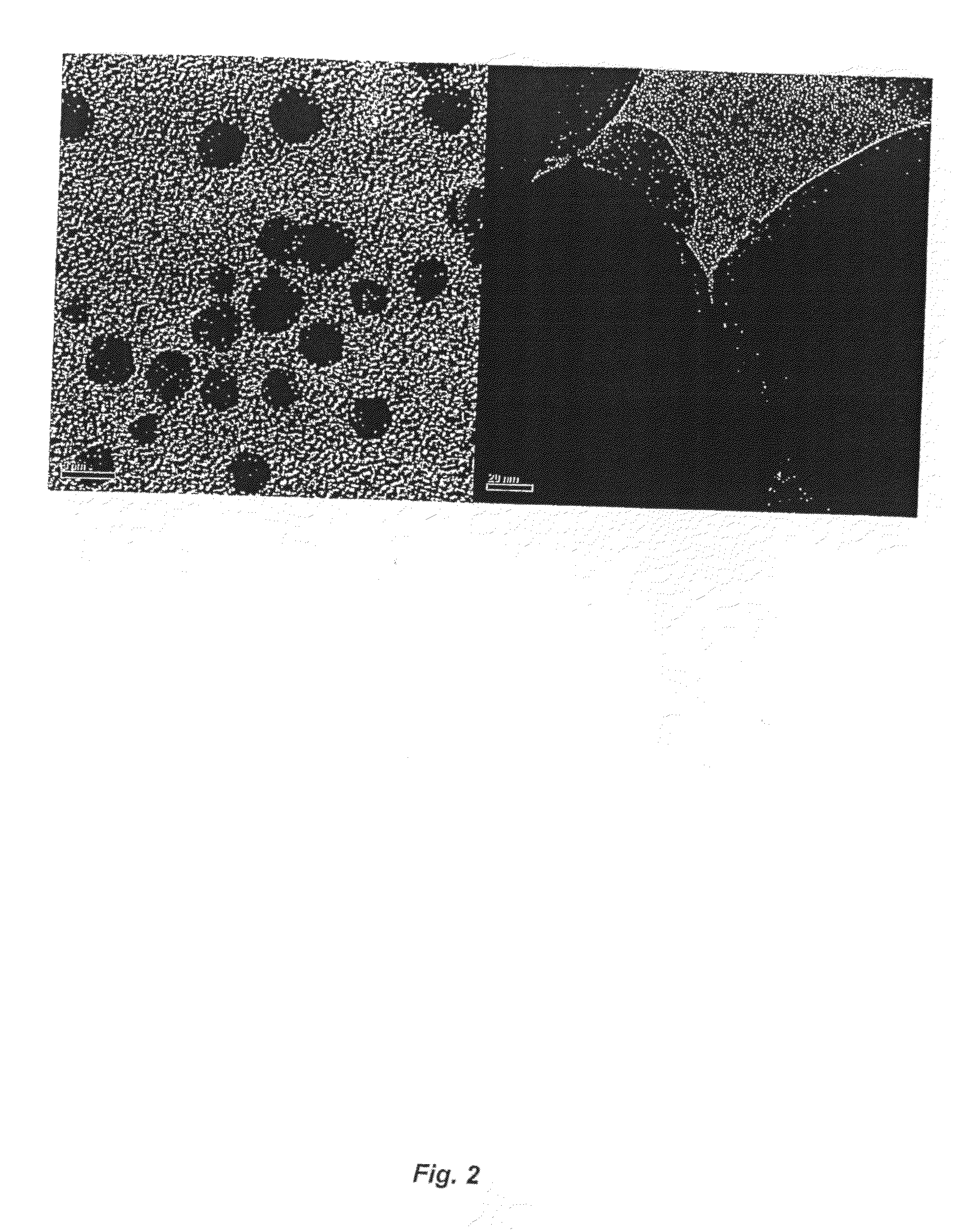
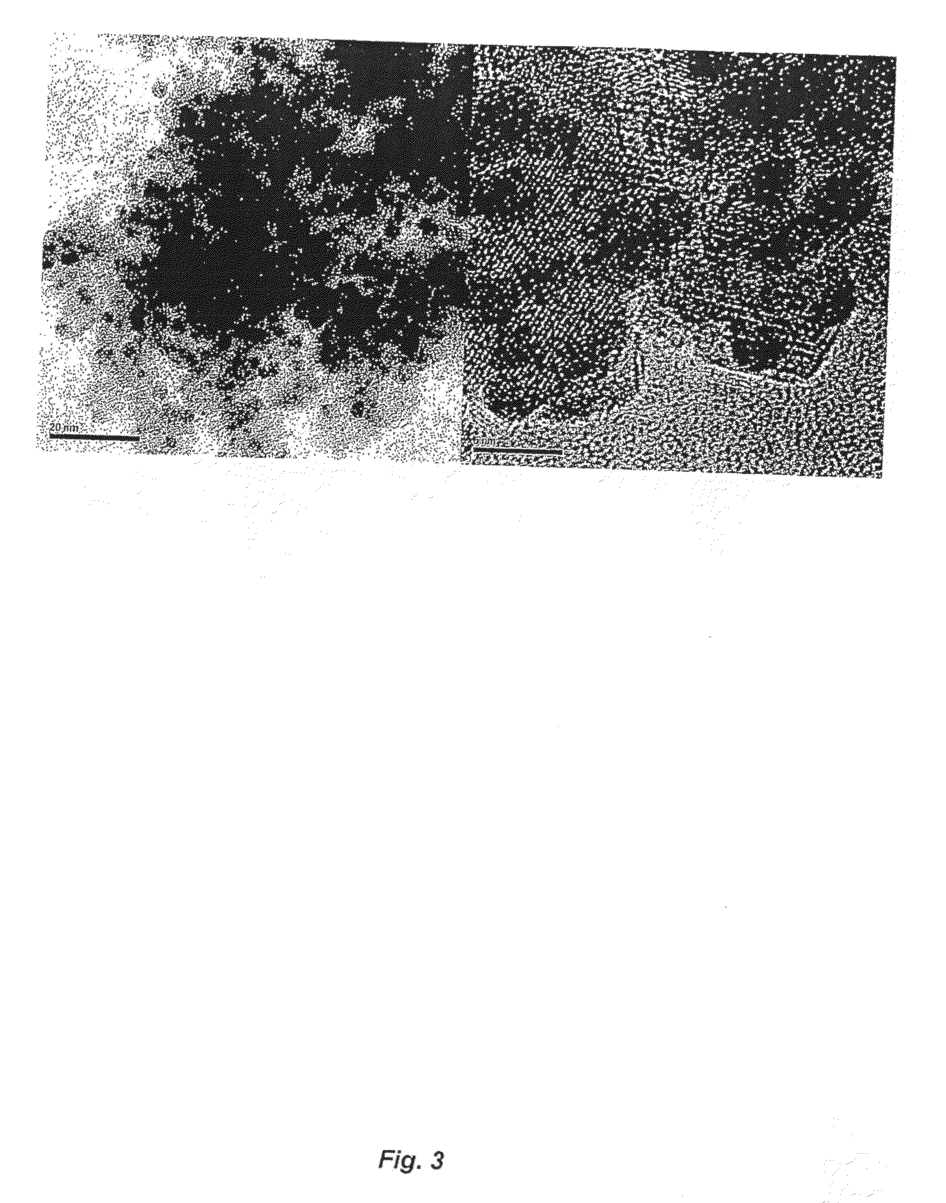
[0068]TEM images of the catalysts of Au / TiO2, Au / Fe2O3, Au / SiO2, (B) Au / CeO2, (C) Au / Al2O3, Pt / TiO2 are presented in FIGS. 2, 3, 4 and 10, respectively. The Au colloids are 3-5 nm in diameter in the solution (FIG. 2A). After deposited onto TiO2 (FIG. 2B), or Fe2O3, or other catalyst supports, there is almost no change in size for Au particles. Also, these Au particles are highly dispersed on these catalyst supports (FIG. 2B, FIG...

example 2

Activity Comparison of the Catalysts of the Present Invention with the Best Literature Results

[0069]

TABLE 1A comparison of preparation conditions and results of our catalyst with best literature results.CO content (ppm)Au particleCatalystafter reaction inCO in airbMethodTemp (° C.)Time (hr)size (nm)loading (%)reactant gasa(ppm)ICESRT0.53-5170-80(Au / Fe2O3)ICESRT0.53-55(Au / Fe2O3)Co-Pc802-33.7550no datad(Au / Fe2O3)D-Pc804-8  1-3.36-8poorc(Au / TiO2)PcRT~12-33no(Au / Fe2O3)aReactant gas contains 1% CO, 1-2% O2, 77% H2, 20% CO2.bReactant gas is 1% CO in air (10,000 ppm).c“Co-P” refers to Co-precipitation method (Landon, P., et al. Chem. Commun. 2005, 3385); “D-P” refers to Deposition -precipitation method (Zanella, R. et al., J. Phys. Chem. B 2002, 106, 7634); “P” refers to Precipitation method (Cheng, W. H. et al., Catalysis Today, 2004, 97, 145).dNo catalytic data reported in Landon, et al, One sample was prepared and tested by the inventors.

example 3

Oxidation of CO in Air for Mask Application

[0070]The oxidation of CO in air on Au / TiO2 and on 1% Au / Fe2O3 are presented in FIG. 5 and FIG. 6, respectively. Complete removal of CO can be achieved at room temperature for the two catalysts under high space velocity, and at 0° C. for 1% Au / Fe2O3 catalyst. However, at −63° C., the CO conversion decreased to ca. 2.35% from 100% on 1% Au / Fe2O3 (FIG. 6B). The test shows that the life of the catalyst is at least longer than 200 hrs. Further testing of the stability was not conducted. Both 1% Au / TiO2 and 1% Au / Fe2O3 are suitable for the application in mask and other breathing devices.


PUM

PropertyMeasurementUnit
temperatureaaaaaaaaaa
operating temperatureaaaaaaaaaa
flow rateaaaaaaaaaa

Abstract

The present invention relates to a novel method for preparing a new type of catalyst for the oxidation of CO in a reactant gas or air. The method provides the preparation of a catalyst having nano-sized metal particles and a capping agent deposited on a solid support. The size and distribution of the metal particles can be easily controlled by adjusting reaction condition and the capping agent used. The catalyst prepared has high activity at low temperature toward selective oxidation of CO and is stable over an extended period of time. The catalyst can be used in air filter devices, hydrogen purification processes, automotive emission control devices (decomposition of NOx, x is the integer 1 or 2), F-T synthesis, preparation of fuel-cell electrode, photocatalysis and sensors.

Description

CROSS-REFERENCES TO RELATED APPLICATIONS[0001]This application claims the priority to U.S. Provisional Patent Application No. 60 / 736,259, filed Nov. 14, 2005, which is hereby incorporated by reference in its entirety for all purposes.BACKGROUND OF THE INVENTION[0002]Nanotechnology has generated a great impact on materials, microelectronics, computing, pharmaceuticals, medicinal, environmental, energy and the chemical industries. Nanocatalysts are an important part of nanotechnology which have found increasing commercial applications. Suitable areas include pollution and emission control technologies, such as automotive pollution abatement, catalytic removal of volatile organic compounds (VOCs) in indoor environment and low temperature air purification. Applications include, for example, using mask filters to burn CO at room temperature, chemical processing of a range of bulk and specialty chemicals, sensors to detect poisonous or flammable gases or substances in solution, and the em...

Claims


Application Information

Patent Timeline
Patent Type & Authority Applications(United States)
IPC IPC(8): B01J23/52B01J23/00B01J29/068B01J31/06B01J21/18B01J21/08B01J23/10B01J37/34B01D53/62
CPCB01J23/42B01D53/864B01J31/02B01J31/0237B01J2231/70B01J23/8906B01J31/06B01J31/04B01J37/16B01J23/52B01D53/944B01J35/0013B01D2255/106B01J35/006B01J31/065B01D53/86B01J23/40B01J35/00
Inventor ZHONG, ZIYILIN, JIANYI
Owner AGENCY FOR SCI TECH & RES
Why Eureka
Try Eureka