[0008]An embodiment of this invention allow work in a medical environment wherein a pressure-differential is expected. Certain embodiments of the invention will prevent air from entering and / or the escape of blood or other body fluids when a
high pressure system (defined as above atmospheric) is accessed by interventional techniques.
[0009]For example, disclosed in one embodiment is an air block, or air trap, module that is affixed to the proximal end of a primary sheath, said primary sheath intended for
vascular access. The module is generally disposable and can be provided integral to the primary sheath, permanently attached to the primary sheath, or removably attached to the primary sheath. The module permits introduction of catheters or other
instrumentation through the central lumen of the primary sheath. In one embodiment, the module further substantially prevents the loss of blood when the distal end of the catheter is exposed to circulating blood, either in the arterial or venous
system. The module traps substantially any air entrained into its interior lumen, prevents the air from entering the through lumen of the primary catheter, and shunts the air out of the interior lumen of the module through an air exit port.
[0010]In other embodiments, the invention is applicable to industrial uses where the blocking of gasses is desired. For example, an embodiment of the invention prevents gas from entering and / or the escape of gas of other materials from a vessel when a
high pressure system is accessed.
[0012]In other embodiments directed to industrial or non-medical uses, the catheter ports are replaced with a wide variety of different types of ports. Also, instead of a catheter, an embodiment of the invention can be adapted to receive a variety of devices such as tubular devices for
insertion into containers, canals, vessels, passageways, or the like. Such devices can be designed, for example, to permit injection or withdrawal of fluids or to keep a passage open. For example, an embodiment of the invention directed to industrial uses prevents gas from entering and / or the escape of gas of other materials from a vessel when a device is inserted into the vessel.
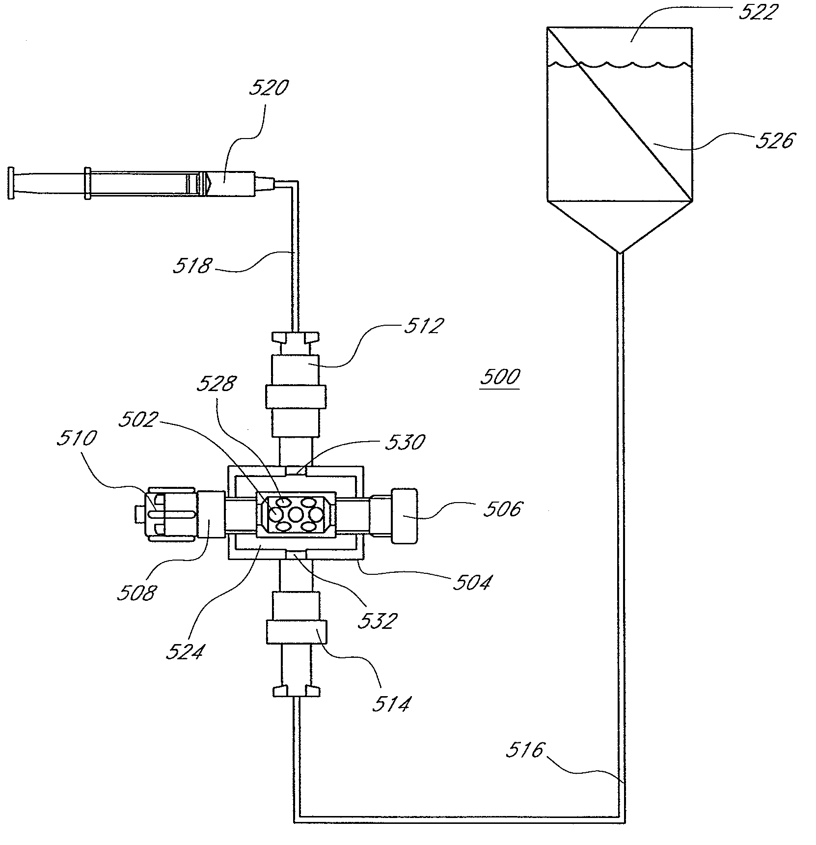
[0014]The air block, or air removal system, can be operably connected to an external subsystem that provides a reservoir of liquid such as water,
saline,
Ringers solution, or the like pressurized to a level above that of the
venous pressure. The fluid delivery subsystem is operably connected to the fluid inlet port of the air block by way of a tube, manifold, or the like. The air block can also be operably connected to an external subsystem that withdraws or removes gas, specifically air, which can collect within the shell of the air block. The gas removal subsystem is operably connected to the shell of the air block by the gas removal port. Although the subsystems are referred to as being external, they can also be internal, integral to, or affixed to the air block module. In an embodiment, the gas removal subsystem can comprise a gas permeable membrane that permits gas such as air to pass but substantially prevents the loss of liquids such as water,
saline, or blood. In this embodiment, a pump is operably connected to withdraw the air out of the trap through the as permeable membrane by generating a pressure drop within a range that facilitates such air passage.
[0016]Another aspect of the invention is the method of use of the bubble, gas, or air block apparatus. The air block is affixed to the proximal end of the primary catheter, cannula, introducer, or sheath. The primary catheter is flushed with
saline and purged of air. The primary catheter is introduced into the vascular system, generally after first placing a guidewire, which is routed through the central lumen of the air block. The fluid inlet port of the air block is connected to a source of normal saline. The gas outlet port of the air block can be connected to a fluid removal system. The primary catheter is routed to its target location. The secondary catheter, or catheters, can be inserted through the proximal most
hemostasis valve of the air block, through the central lumen of the core tube of the air block, through the secondary air block
hemostasis valve, through the catheter lumen and into the vascular system at the
target site. Any air that becomes entrained into the core tube of the air escapes through perforations in the core tube and migrates into the larger
diameter shell. The
trapped air either remains within the larger
diameter shell or it is drawn off by the fluid removal system either into the air or into an air reservoir. The fluid removal system can be optimized to selectively withdraw only gasses such as air. This selective withdrawal of air can be performed using a microporous membrane fabricated from materials such as, but not limited to,
polypropylene,
polyethylene, polytetraflouoroethylene, other
polyolefin,
polyester, or the like. The membrane can have porous structures that penetrate from one side of the membrane to the other and with a size of about 100 microns with a range of 50 microns to 1000 microns. The pore density and pore size can be selected to be compatible with a pressure drop across the membrane, as generated by a pump or other suction (vacuum) or pressure generating device so as to remove a given volume of air over a specified length of time without the loss of a substantial amount of liquid such as blood.

