Process And Apparatus For Depositing Semiconductor Layers Using Two Process Gases, One Of Which is Preconditioned

a technology of process gas and semiconductor layer, applied in the direction of electrical apparatus, chemical vapor deposition coating, coating, etc., can solve the problems of high consumption, high cost of process used to date, and low mass flow of carrier gas, so as to reduce the mass flow of hydride, the effect of low cost and reduced mass flow

Inactive Publication Date: 2010-01-21
STRAUCH GERHARD KARL +3
View PDF66 Cites 7 Cited by
  • Summary
  • Abstract
  • Description
  • Claims
  • Application Information

AI Technical Summary

Benefits of technology

[0010]Working on the basis of the situation which has been outlined above, whereby the light-emitting diodes produced using the known processes are not in widespread use for cost reasons, the invention is based on the object of providing measures which allow the lumen / cost ratio to be considerably enhanced.
[0011]The light yield with respect to the production costs incurred is improved, according to the invention, by virtue of the fact that only the second process gas, which is introduced into the process chamber separately from the first process gas, is preconditioned before it enters the process chamber. The decomposition products enter the process chamber at the edge of the substrate holder, immediately above it, and within the diffusion boundary layer diffuse parallel to the substrate holder surface. The apparatus which is proposed according to the invention for carrying out this process is distinguished by the fact that a preconditioning apparatus is disposed at the edge of the substrate holder for preconditioning purposes. The substrate holder is preferably in the shape of a ring, and the ring can rotate about its center. The preconditioning apparatus is then located in the center of this ring (at the ring inner edge). However, there is also provision for the process chamber to be linear in form or in the shape of a funnel. In this case, the substrate holder is preferably in the shape of a rectangle or a trapezoid. The preconditioning device is then located upstream of the susceptor. The first process gas (metal alkyl), which is preferably trimethylgallium, is introduced into the process chamber through a multiplicity of openings. In this case, the openings are located in the wall which lies directly opposite the substrate holder. The direction in which the gas flows in extends transversely with respect to the surface of the substrate holder. The direction in which the gas flows out extends transversely with respect to the direction in which the gas flows in and parallel to the substrate surface, i.e. parallel to the wall. This wall forms a gas inlet member in showerhead form. Further openings, through which a carrier gas, for example hydrogen or nitrogen, flows into the process chamber, are disposed in the top of the process chamber, upstream and / or downstream of the gas inlet member based on the direction in which the gas flows out, which is oriented parallel to the surface of the substrate holder. The flow of this carrier gas is matched to the flow of the carrier gas which flows in through the openings in the gas inlet member, in such a manner as to form a diffusion / flow boundary layer which is as flat as possible above the substrate holder. In this case, the flow / diffusion boundary layer is as far as possible in the lower half of the process chamber. The preconditioned second process gas is injected into the process chamber in the form of radicals within this diffusion / flow boundary layer. To produce the radicals, the preconditioning apparatus preferably has a plasma generator or a hot-wire apparatus or catalytic device or a combination of the above. This is used to heat the second process gas to temperatures which are such that it decomposes to a high degree.
[0013]In addition, it is also possible for a considerably greater mass flow of a carrier gas to be introduced into the gas inlet member. The mass flow of the nitrogen or hydrogen used for this purpose may amount to approximately 30 slm. On account of the virtually complete decomposition of the second process gas within the preconditioning apparatus, the supply of decomposition products of the second process gas in the gas phase immediately above the substrate surface is nevertheless greater than the supply of the decomposed or undecomposed first process gas, which in addition to TMG may also be TMI or other metal alkyls. The process temperatures can be varied within a wide range. They may be between 400° C. and 1600° C. The adverse effect on the temperature profile within the process chamber caused by a thermally preconditioned second reaction gas is negligible, on account of the relatively low mass flow and heat capacity. It is important that the diffusion of the preconditioned hydrides be directed transversely with respect to the alkyl gas stream emerging from a CCS showerhead. The carrier gas which emerges from the showerhead together with the alkyl gas hydrodynamically compresses the flow of the preconditioned hydrides onto the crystal growth surface. The high quantity of carrier gas stream substance resulting from it being fed in via the gas inlet member leads to such a high dilution of the hydrides at the location of the surface of the gas inlet member that the reaction equilibrium for the formation of parasitic deposits on the gas inlet member is well below 1. The result of this is that there can be longer intervals between cleaning of the process chamber than the intervals required in the prior art. On account of the proposal according to the invention, the mass flow of the hydride is reduced by a factor of 100 compared to the prior art. At the same time, this reduces the defect density in the deposited layers, so that light-emitting diodes (GaN) which emit in the UV, produced in this way, can be operated with a higher current, i.e. with a higher light yield.

Problems solved by technology

The processes used hitherto are expensive, since the outlay on materials, in particular with regard to the nitrogen hydride, is considerably higher than the outlay on materials for the metal alkyl, for example TMG.
Although the hydrides are relatively inexpensive compared to the alkyls, the consumption costs are approximately the same, on account of the high consumption.
The high consumption is a result of the high thermal activation energy of the hydrides compared to the activation energies of the metal alkyls.

Method used


Image

  • Process And Apparatus For Depositing Semiconductor Layers Using Two Process Gases, One Of Which is Preconditioned
  • Process And Apparatus For Depositing Semiconductor Layers Using Two Process Gases, One Of Which is Preconditioned
  • Process And Apparatus For Depositing Semiconductor Layers Using Two Process Gases, One Of Which is Preconditioned

Examples


Embodiment Construction

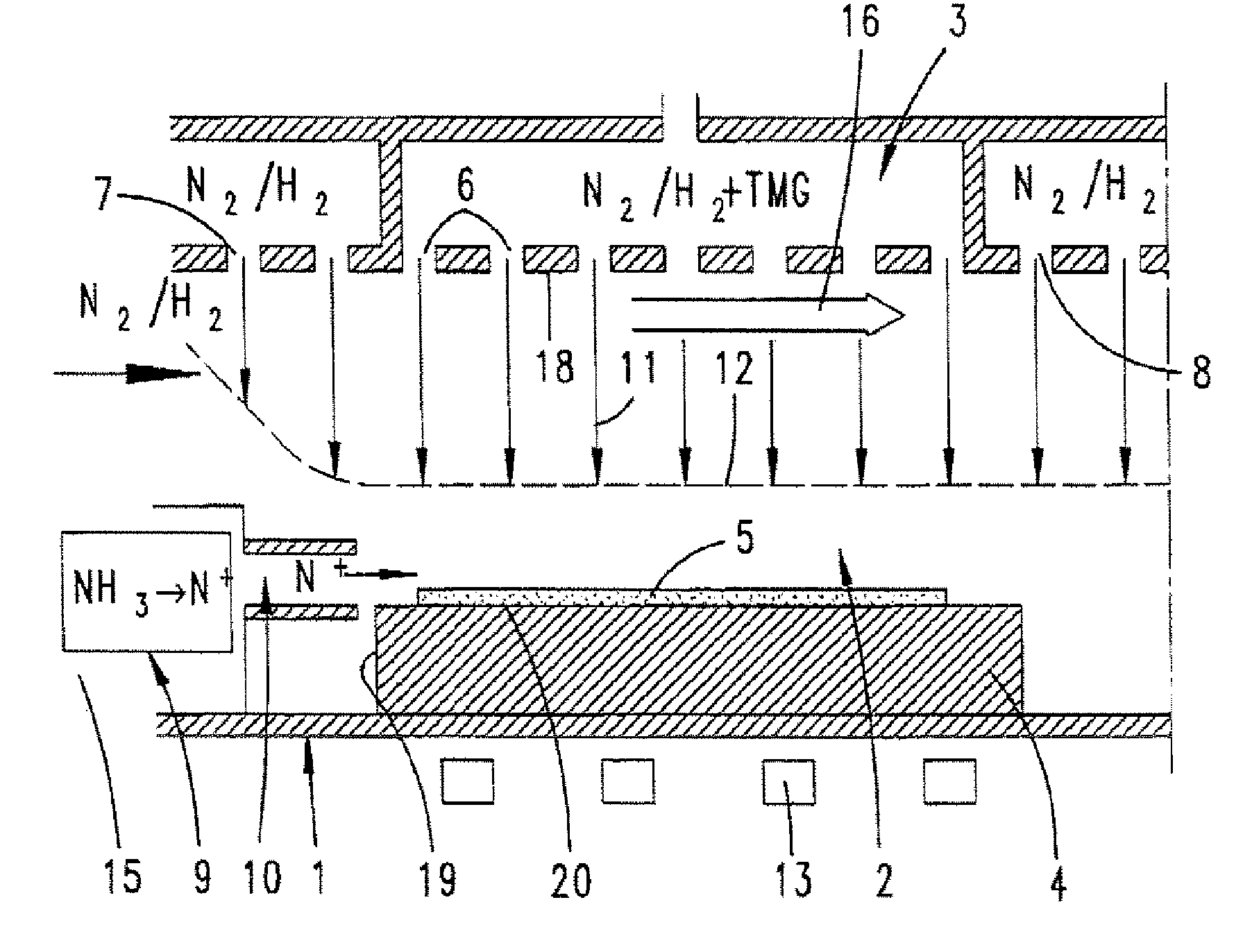
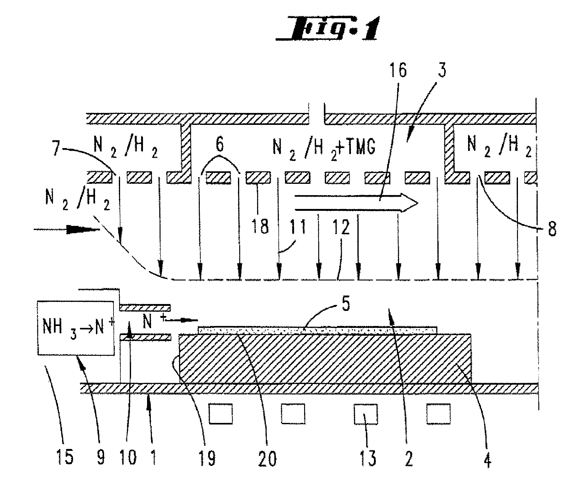
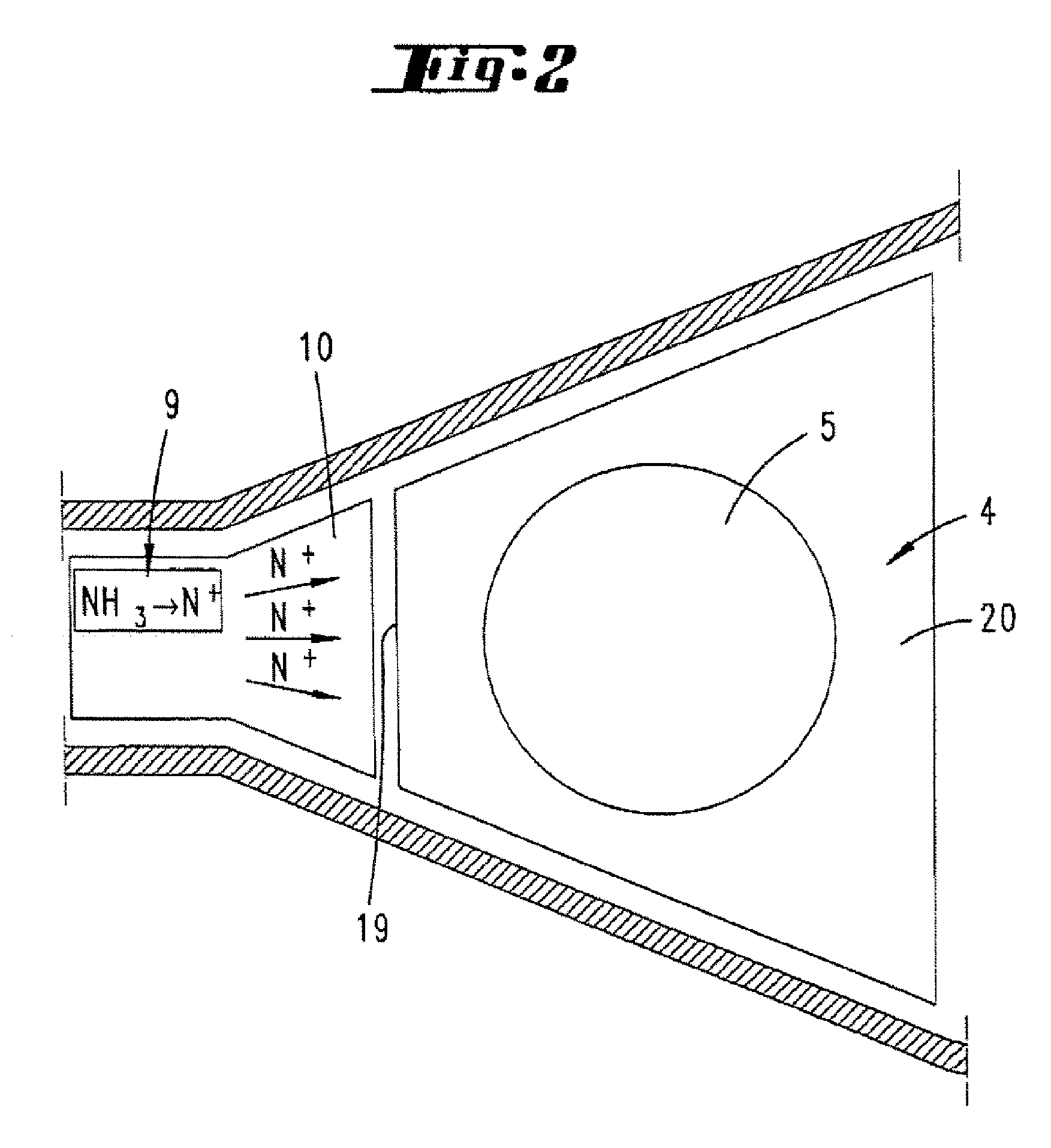
[0024]The reactor 1 illustrated in FIG. 1 has a housing (not shown). Within the housing of the reactor 1 is a heating device 13 which can be used to heat a substrate holder 4 to process temperature. A substrate, on which a layer is to be deposited, is located on the substrate holder 4. It is also possible for there to be a multiplicity of substrates 5 on the substrate holder 4.

[0025]The process chamber 2 is located above the substrate holder 4. The process chamber 2 is delimited at the top by a gas inlet member 3. This gas inlet member 3 forms a gas exit surface 18, which extends parallel to the surface 20 of the substrate holder 4. Gas entry openings 6 are located in the gas exit surface 18 in known manner. These gas entry openings 6 are distributed over the gas exit surface 18 in such a manner that the gas jets which emerge from the gas entry openings 6 and enter the process chamber in the gas inflow direction form a uniform gas flow field in the direction of the substrate holder ...


PUM

PropertyMeasurementUnit
heightaaaaaaaaaa
heightaaaaaaaaaa
heightaaaaaaaaaa

Abstract

A method and device for depositing at least one layer, particularly a semiconductor layer, onto at least one substrate, which is situated inside a process chamber of a reactor while being supported by a substrate holder, is provided. The layer includes of at least two material components provided in a fixed stoichiometric ratio, which are each introduced into the reactor in the form of a first and a second reaction gas, and a portion of the decomposition products form the layer, whereby the supply of the first reaction gas, which has a low thermal activation energy, determines the growth rate of the layer, and the second reaction gas, which has a high thermal activation energy, is supplied in excess and is preconditioned, in particular, by an independent supply of energy.

Description

PRIOR APPLICATIONS[0001]This application is a divisional patent application of U.S. patent application Ser. No. 11 / 262,874 for a “Process And Apparatus For Dispositing Semiconductor Layers” filed on Oct. 31, 2005, which is a continuation of International Patent Application No. PCT / EP2004 / 002994 filed on Mar. 22, 2004, which designates the United States and claims priority of German Patent Application No. 10320597.7 filed on Apr. 30, 2003.FIELD OF THE INVENTION[0002]The invention relates to a process for depositing at least one layer, in particular semiconductor layer, on at least one substrate carried by a substrate holder in a process chamber of a reactor, the layer consisting of at least two material components which are in a controlled (fixed or varying) stochiometric ratio and are respectively introduced in the form of a first reaction gas and a second reaction gas into the reactor, where the reaction gases are chemically decomposed as a result of a supply of energy, and some of...

Claims


Application Information

Patent Timeline
Patent Type & Authority Applications(United States)
IPC IPC(8): C23C16/513C23C16/46C23C16/30C23C16/44C23C16/452C23C16/455
CPCC23C16/303C23C16/452Y10S438/905C23C16/45574C23C16/45514H01L21/0262H01L21/0254
Inventor STRAUCH, GERHARD KARLKAEPPELER, JOHANNESREINHOLD, MARKUSSCHULTE, BERND
Owner STRAUCH GERHARD KARL
Why Eureka
Try Eureka