Digital delay line and application thereof

a delay line and digital delay technology, applied in the field of delay lines, can solve the problems of very high phase jitter, and achieve the effect of reducing the area of delay lines and power consumption

Inactive Publication Date: 2010-01-21
NAT CHIAO TUNG UNIV
View PDF6 Cites 7 Cited by
  • Summary
  • Abstract
  • Description
  • Claims
  • Application Information

AI Technical Summary

Benefits of technology

[0006]The present invention is directed to a delay line and its application in a digital circuit. The

Problems solved by technology

The most difficult problems in application specific integrated circuit (ASIC) design often involve meeting system I/O timing demands.
Digital phase locked loops do not adjust delays of any ga

Method used


Image

  • Digital delay line and application thereof
  • Digital delay line and application thereof
  • Digital delay line and application thereof

Examples


Embodiment Construction

[0017]The embodiments of the present invention are illustrated in reference to the drawings.

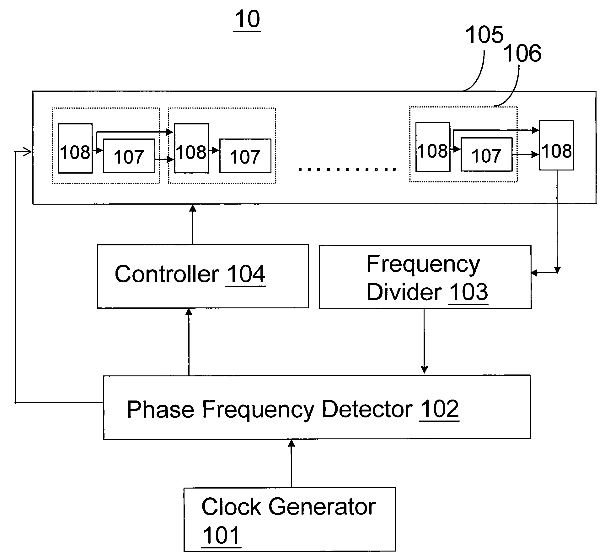
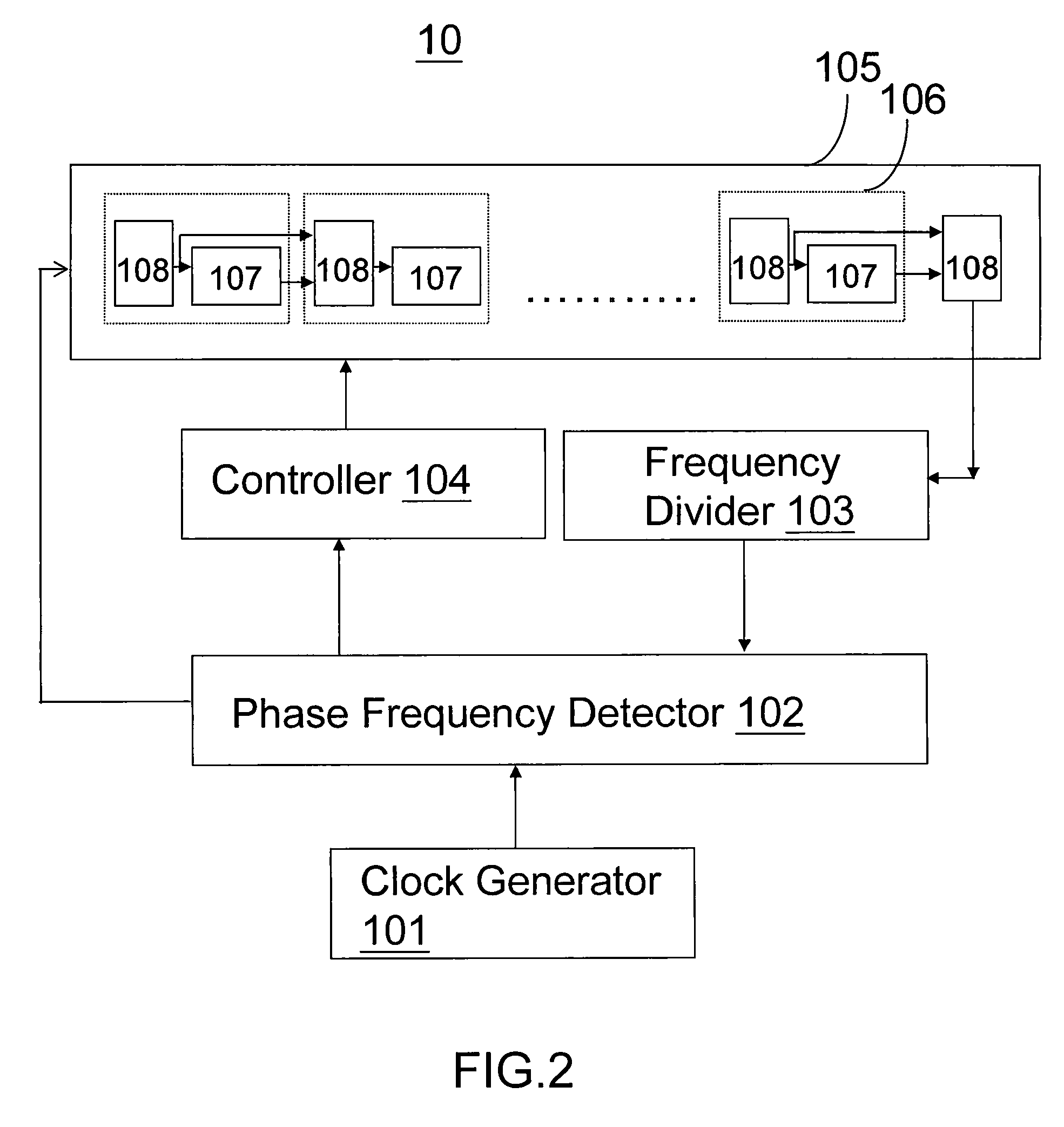
[0018]There are various examples configured for illustrating a hysteresis-based delay cell (HDC) as basis of a delay line. Such a delay line may be applied to, but not limited to, a digitally-controlled oscillator (DCO), all-digital phase-locked loops (ADPLL), all-digital delay-locked loops (ADDLL), all-digital multi-phase clock generator (ADMCG) and digital phase-locked loops based applications. Next, the spirit of the present invention is illustrated with the exemplary hysteresis-based delay cells without the limitation on components and connection hereafter.

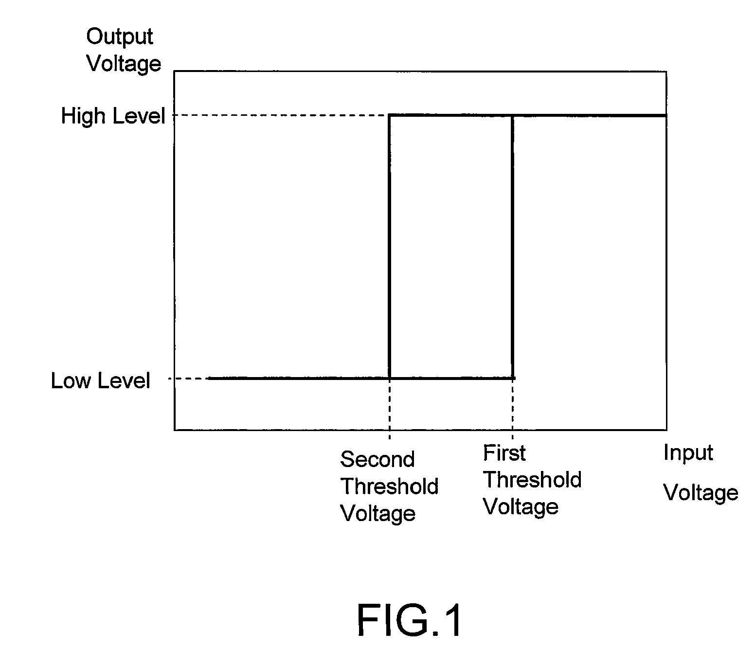
[0019]Referring to FIG. 1, the hysteresis delay unit is hysteresis-based including a circuit with a low level voltage as a first input voltage. When the first input voltage of the circuit reaches a first threshold voltage, an output voltage (first output constant voltage) is sharply inverted from a low level constant voltage to a high l...


PUM


Abstract

A digital delay line includes a plurality of hysteresis-based delay cells electrically connected in series. These hystersis delay units in the hysteresis-based delay cells may be similar or different. All of the hysteresis delay units respectively have an inverter mode and a hesteresis mode. The delay and resolution of the hysteresis delay unit may be derived from the time difference in the inverter mode and hysteresis mode. Such a digital delay line applied to a digital phase locked loop may reduce consumption of area and power.

Description

BACKGROUND OF THE INVENTION[0001]1. Field of the Invention[0002]The present invention relates to a delay line and application thereof, and more particularly, to a delay line comprising hysteresis delay cells and its application in digital phase-locked loops.[0003]2. Description of the Prior Art[0004]The most difficult problems in application specific integrated circuit (ASIC) design often involve meeting system I / O timing demands. IC delays can vary by 200-400% over all voltage, temperature, and process conditions. If this delay can be controlled, systems can be designed which more fully exploit the innate performance capabilities of their semiconductor components. It is important to minimize on-chip clock distribution delay and total system clock skew in a system which uses ASICs in order to provide for safe data transfer between the ASICs. ASIC Phase Locked Loops (PLLs) are used most commonly to eliminate on-chip clock distribution delay. PLLs can eliminate delay in clock bufferin...

Claims


Application Information

Patent Timeline
IPC IPC(8): H03L7/06H03H11/26
CPCH03H11/265H03K3/3565H03L2207/50H03L7/0812H03L7/0995H03K5/133H03L7/0814
Inventor LEE, CHEN-YIYU, JUI-YUANCHEN, JUINN-TING
Owner NAT CHIAO TUNG UNIV
Why Eureka
Try Eureka