
Athermal external cavity laser

a laser and external cavity technology, applied in the field of external cavity lasers, can solve the problems of affecting the efficiency the amount by which the optical transmission module can be reduced to a certain limit, and the increase of the price of the optical transmission module including the monitoring photodetector and the wavelength fixing unit, so as to achieve the effect of low cos

Inactive Publication Date: 2010-01-21
ELECTRONICS & TELECOMM RES INST
View PDF3 Cites 18 Cited by
  • Summary
  • Abstract
  • Description
  • Claims
  • Application Information

AI Technical Summary

Benefits of technology

The athermal ECL ensures regular output optical power and wavelength stability across temperature changes, reducing manufacturing costs and improving the reliability of WDM PON systems by eliminating mode hopping and the need for expensive temperature control modules.

Problems solved by technology

Accordingly, the allowable range of wavelength error of a light source that may occur with respect to the external temperature is strictly limited in the WDM system.
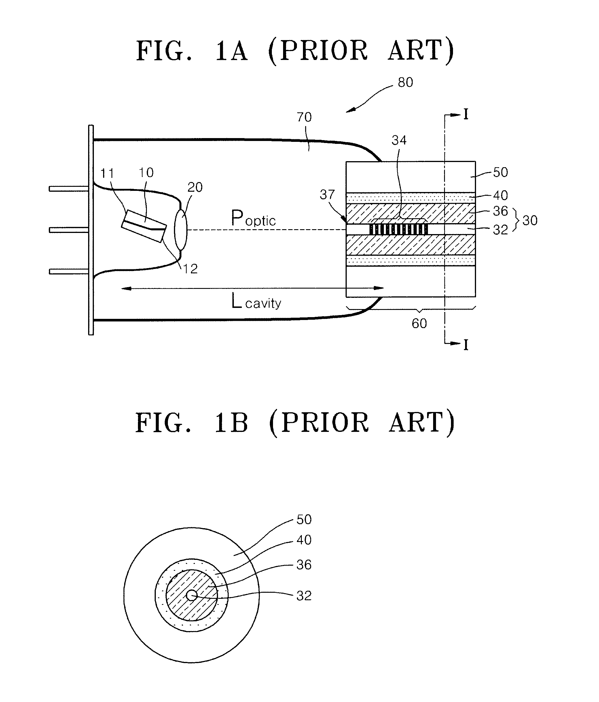
However, since controlling components such as a TEC, a thermistor, a heat dissipating plate, a temperature controlling circuit, etc. need to be additionally attached to the DFB lasers, and an expensive butterfly type package should be selected, the amount by which the price of the optical transmission module can be reduced reaches a certain limit.
Also, since it is difficult to apply the optical transmission modules including a monitoring photodetector and a wavelength fixing unit to a PON, the greatest advantage of which is its price competitiveness, a monitoring photodetector and a wavelength fixing unit should be added to stabilize the oscillation and the optical output, and this raises the price of the optical transmission modules including a monitoring photodetector and a wavelength fixing unit.
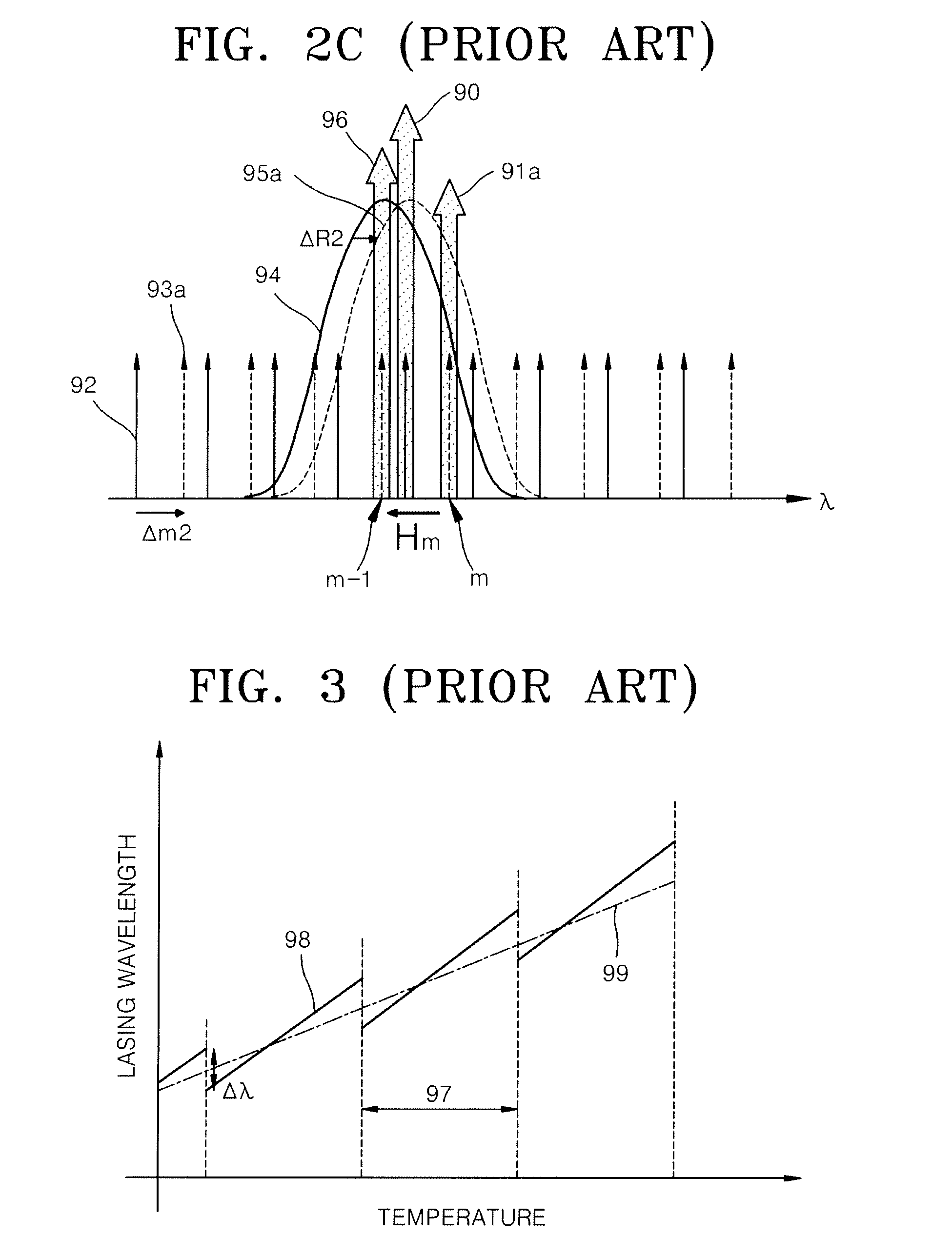
Such rapid change in optical power not only rapidly deteriorates the transmission quality of the WDM PON but also rapidly deteriorates long-term reliability of a device.

Method used


Image

  • Athermal external cavity laser
  • Athermal external cavity laser
  • Athermal external cavity laser

Examples


Embodiment Construction

[0054]The present invention will now be described more fully with reference to the accompanying drawings, in which exemplary embodiments of the invention are shown.

[0055]It will be understood that when a layer is referred to as being “on” another layer or substrate, it can be directly on the other layer or substrate, or intervening layers may also be present. In the drawings, the thicknesses of layers and regions are exaggerated for clarity and portions not related to the description are omitted. Like reference numerals in the drawings denote like elements. The terms used are for illustrative purpose of the present application only and are not intended to limit the scope of the present invention described in the claims.

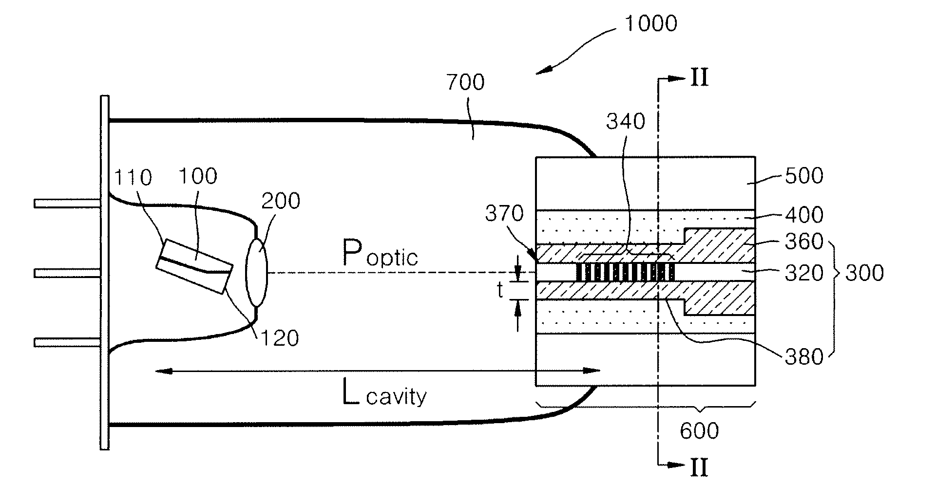
[0056]For the output optical power to be athermal, reflection spectrums of a Bragg grating should be regular, and for this, the wavelength change according to the temperature of a Bragg grating 99 in FIG. 3, that is, ∂λWBG / ∂T, should be lowered. ∂λWBG / ∂T is reduced by...


PUM


Abstract

Provided is an athermal external cavity laser (ECL), whose output optical power and output wavelength can be kept regular irrespective of temperature changes without using additional temperature controlling components. The ECL comprises: a semiconductor amplifier; an optical fiber comprising a core in which a Bragg grating is formed and a cladding surrounding the core; and a thermosetting polymer that fixes the optical fiber to a ferrule and has a negative thermooptical coefficient, wherein the thickness of the cladding surrounding the core in which the Bragg grating is formed is smaller than the portion of the cladding surrounding the portion of the core where the Bragg grating is not formed, and the thermosetting polymer the negative thermooptical coefficient surrounds the cladding. The ECL does not need additional temperature controlling components and thus can be manufactured compact and at low cost, and thus can be used as a light source of a dense wavelength division multiplexing (DWDM) system in designing economical WDM passive optical networks (PON).

Description

CROSS-REFERENCE TO RELATED PATENT APPLICATION[0001]This application claims the benefit of Korean Patent Application No. 10-2005-0119063, filed on Dec. 7, 2005 and Korean Patent Application No. 10-2006-0071649, filed on Jul. 28, 2006, in the Korean Intellectual Property Office, the disclosures of which are incorporated herein in their entirety by reference.BACKGROUND OF THE INVENTION[0002]1. Field of the Invention[0003]The present invention relates to a wavelength division multiplexing (WDM) passive optical network (PON) system, and more particularly, to an external cavity laser (ECL) used as a light source in the WDM PON system.[0004]2. Description of the Related Art[0005]In a general wavelength division multiplexing (WDM) system, the denser the channel spacing, the greater the number of channels. Accordingly, the allowable range of wavelength error of a light source that may occur with respect to the external temperature is strictly limited in the WDM system. In most WDM systems, d...

Claims


Application Information

Patent Timeline
Patent Type & Authority Applications(United States)
IPC IPC(8): H01S3/10
CPCG02B6/0218G02B6/0219G02B6/4206H01S5/02284H01S5/146H01S5/0654H01S5/141H01S5/142H01S5/02288H01S5/02251H01S5/02253
Inventor LEE, JIE HYUNPARK, MAHN YONGJEONG, GEONKIM, CHUL YOUNGCHO, SEUNG HYUNLEE, WOO RAMKIM, BYOUNG WHI
Owner ELECTRONICS & TELECOMM RES INST
Learn More