Membrane electrode assembly for polymer electrolyte fuel cell and polymer electrolyte fuel cell

a fuel cell and membrane electrode technology, applied in the direction of cell components, electrochemical generators, sustainable buildings, etc., can solve the problems of slow discharge of water, so as to improve drainage performance

Inactive Publication Date: 2010-01-21
CANON KK
View PDF4 Cites 15 Cited by
  • Summary
  • Abstract
  • Description
  • Claims
  • Application Information

AI Technical Summary

Benefits of technology

[0031]The present invention has been made in view of the above-mentioned problems, and the present invention provides a MEA for a polymer electrolyte fuel cell, having a structure in which a groove for allowing passage or retention of a fluid is provided in an interface between a catalyst layer and an electrolyte membrane, thereby improving drainage performance.

Problems solved by technology

Further, owing to a high energy density and a low operation temperature of the polymer electrolyte fuel cell, when the polymer electrolyte fuel cell is mounted to small electrical equipment such as a mobile phone, a notebook computer, and a digital camera, the small electrical equipment can be driven for a longer time than a case of using a conventional secondary battery.
However, while the polymer electrolyte fuel cell can be driven at operating temperature of 100° C. or less, there is a problem in that with passage of power generation time, a voltage gradually decreases and power generation stops at last.
In this case, a product water can be discharged to an outside of the fuel cell only by natural evaporation, so the product water tends to be retained in the catalyst layer thereby causing the flooding.
However, when the fuel cell is driven at high current density for a long time, voltage drop of the fuel cell is caused.
As a result, a product water vapor is locally condensed in the holes in the gas diffusion electrode to occupy the holes, thereby causing the local flooding.
Therefore, impregnation of the hydrophobic porous body with water involves a large resistance in theory, so an infiltration rate of the water into the GDL is low.
As a result, a voltage of the fuel cell is reduced by a large amount or the power generation is stopped.
As described above, with a method of imparting the water repellency to the GDL and the catalyst layer, there is a problem in that, in the case where the fuel cell is driven at high load for a long time, the condensed water is retained in the interface between the GDL and the catalyst layer.
Accordingly, it is hard to say that the water repellency of the gas diffusion electrode is effectively improved.
However, with the conventional methods mentioned above, the following problems occur.
In a case of a structure described in Japanese Patent Application Laid-Open No. 2004-327358 and Japanese Patent Application Laid-Open No. 2005-38780, in which concave grooves for drainage are provided in the surface of the catalyst layer, which is brought into contact with the gas diffusion layer, there is a problem in that a catalyst-carrying amount is reduced by an amount corresponding to a volume of the grooves, so a reaction area of the catalyst is reduced, thereby reducing an output density of the fuel cell.
Further, with the structure described in Japanese Patent Application Laid-Open No. 2004-327358 and Japanese Patent Application Laid-Open No. 2005-38780, there is a problem in that, when the grooves are filled with the drain water, an area for suction to the catalyst layer is reduced.
Further, in a case of a structure described in Japanese Patent Application Laid-Open No. 2002-100372, in which the drainage grooves are provided in the surfaces of the GDL on the current collector sides, there is a problem in that, when the grooves are filled with the drain water, the area for suction to the catalyst layer is reduced.
As described in Example 2, in a case where a non-porous material such as metal is used for a diffusion layer substrate, it is difficult for a fuel gas to reach the catalyst brought into contact with the substrate, thereby causing the reaction area of the catalyst to be reduced.
As a result, the flooding can be suppressed, but there is a problem in that, due to reaction gas supply rate control, a limit current density is reduced.
Accordingly, in a case of the fuel cell using the air breathing method in which a porous conductor made of foamed metal or the like is used in place of the separator, there is a problem in that a flooding suppression effect by the above-mentioned structure is obtained only in a restrictive manner.

Method used


Image

  • Membrane electrode assembly for polymer electrolyte fuel cell and polymer electrolyte fuel cell
  • Membrane electrode assembly for polymer electrolyte fuel cell and polymer electrolyte fuel cell
  • Membrane electrode assembly for polymer electrolyte fuel cell and polymer electrolyte fuel cell

Examples


example 1

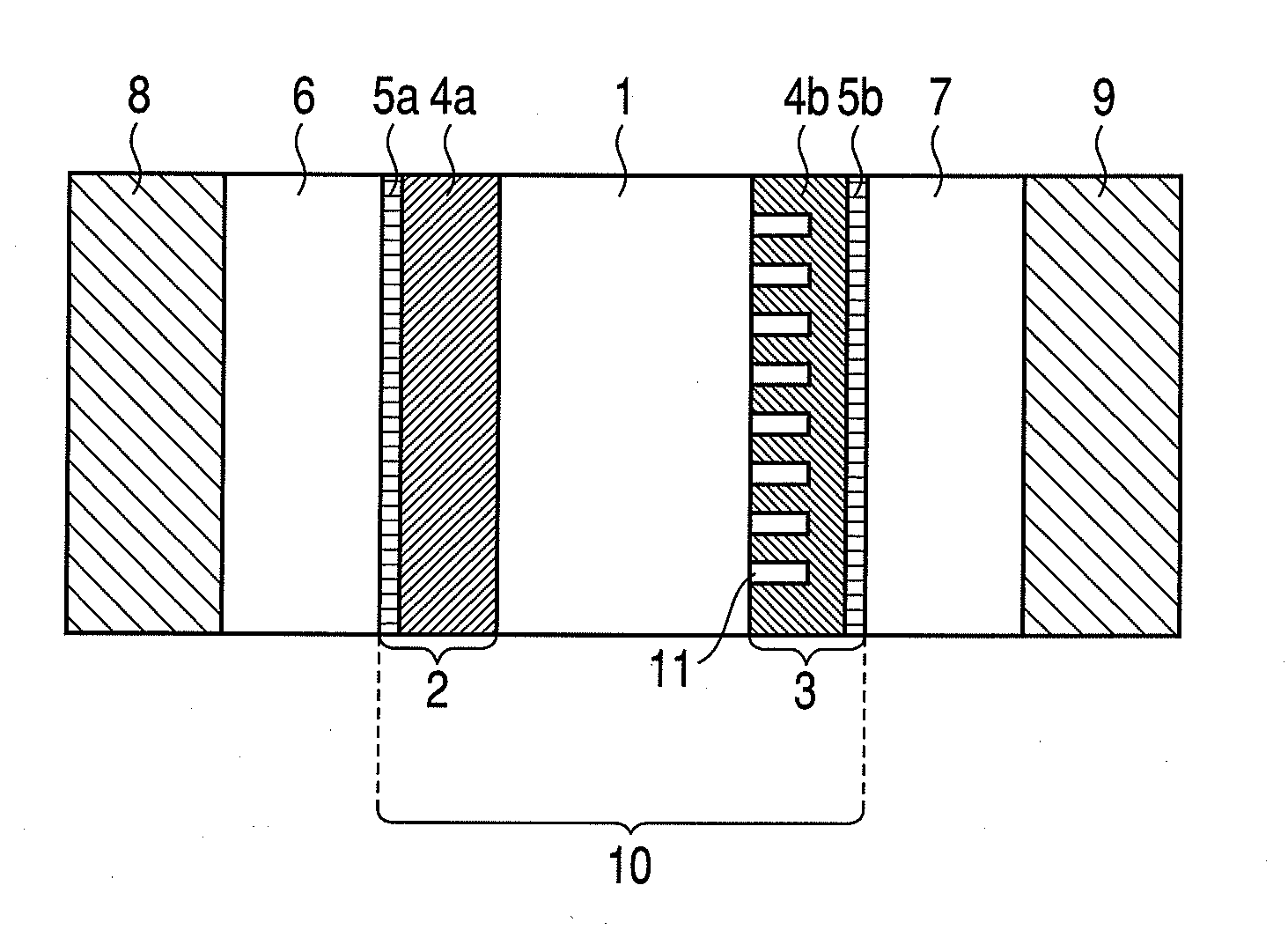
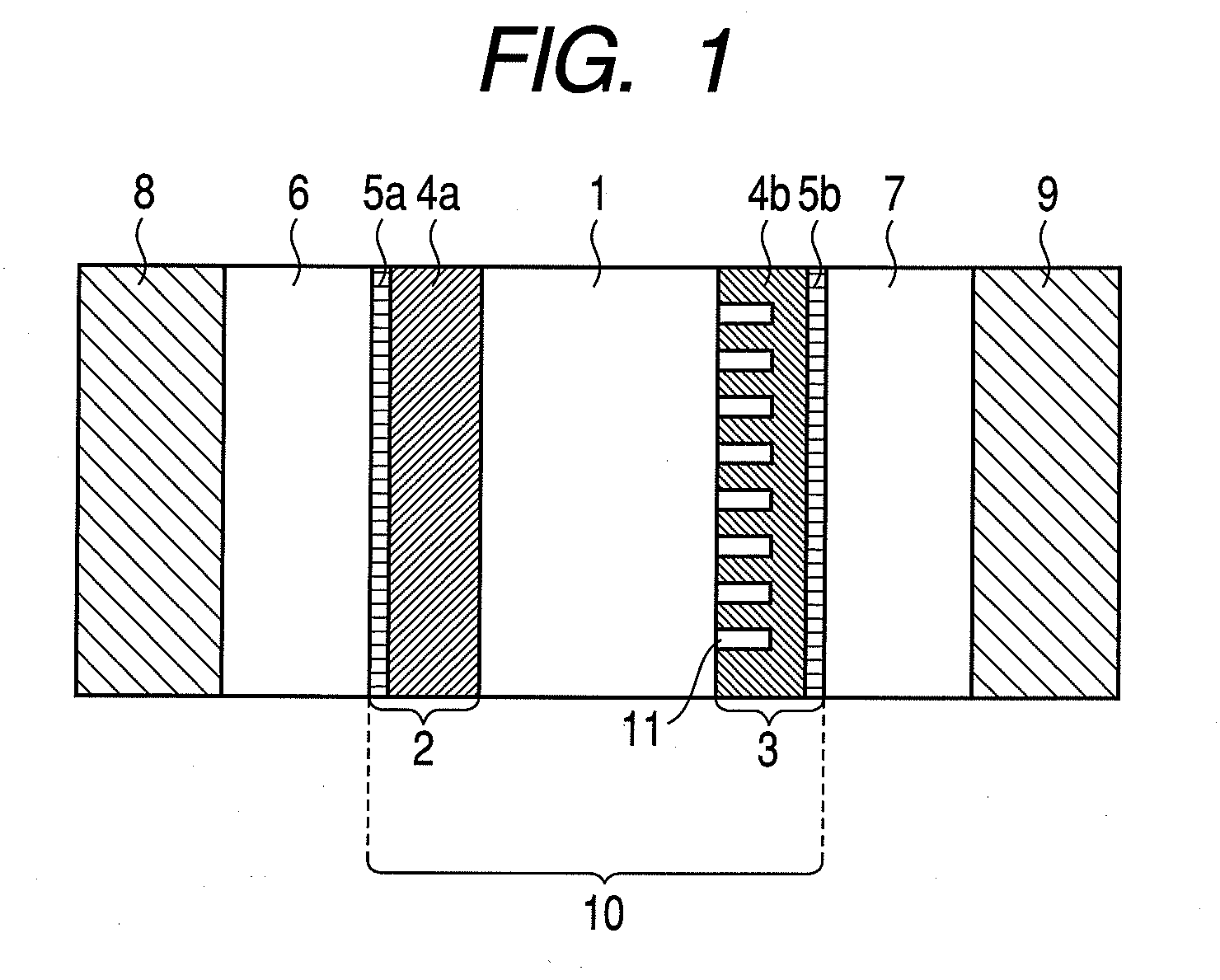
[0093]In this example, there is manufactured a polymer electrolyte fuel cell having the structure illustrated in FIG. 1 of the embodiment.

[0094]Hereinafter, manufacturing steps of the polymer electrolyte fuel cell according to this example will be described in detail.

(Step 1)

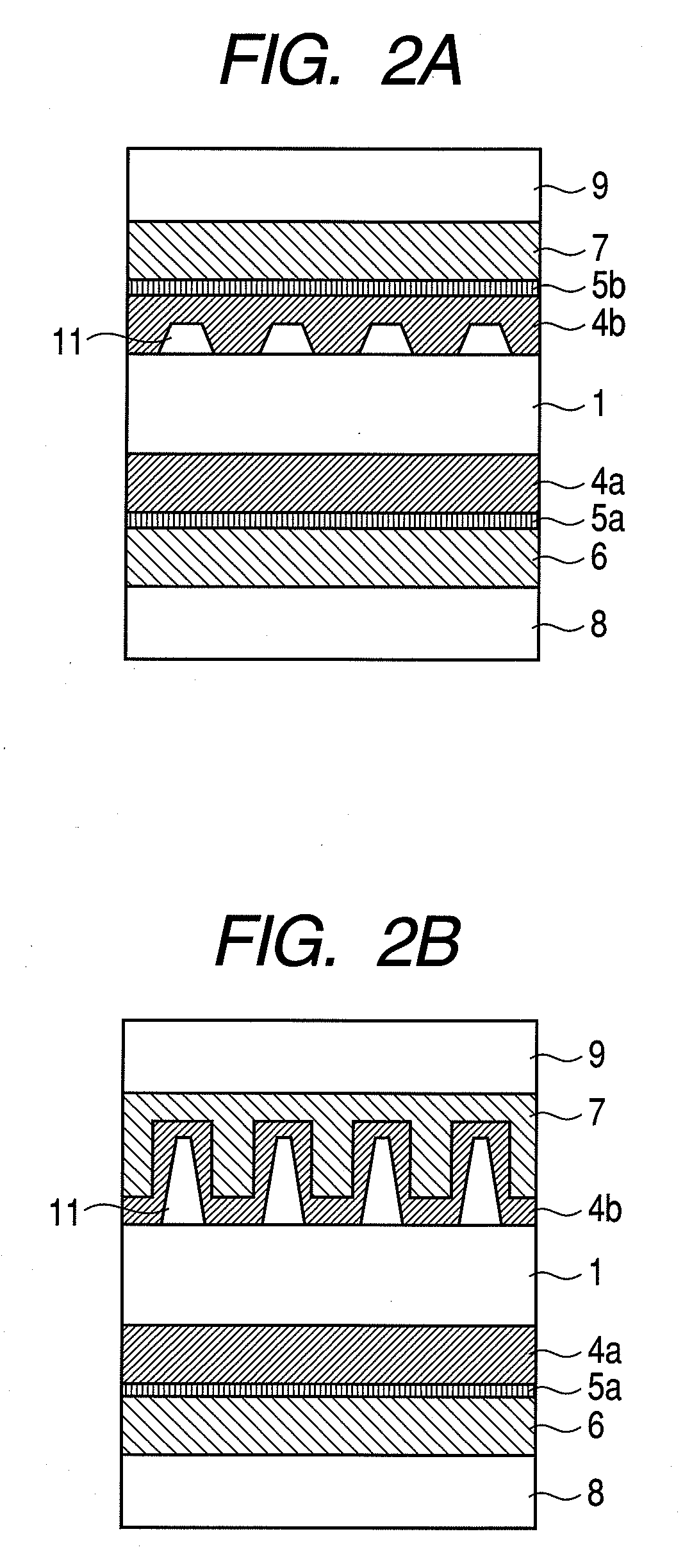
[0095]A surface of a carbon fine particle layer of a carbon cloth (LT1200-W manufactured by E-TEK), was irradiated with YAG laser to machine the surface to have the grooved configuration. An output of the laser was 8 W, a beam size thereof was 10 μm, a pulse width thereof was 3 μm / pulse, and a scanning speed thereof was 15 mm / sec. In order to form the groove having a width of 15 μm, the laser was applied twice for each of the grooves. A second application was performed after shifting an application position by 8 μm in a groove width direction from that of the first application.

[0096]The above-mentioned operations were repeatedly performed to obtain a GDL having a structure in which grooves each having a width of...

example 2

[0112]In this example, there is manufactured a polymer electrolyte fuel cell having the structure illustrated in FIG. 1 of the embodiment.

[0113]Hereinafter, descriptions will be made only of manufacturing processes of the polymer electrolyte fuel cell according to this example, which are different from those of Example 1 in structure and manufacture.

(Step 1)

[0114]A carbon cloth (LT1400-W manufactured by E-TEK) was used as the gas diffusion layer. A surface of the carbon cloth, formed of the carbon fine particles, was irradiated with YAG laser to machine the surface to have the grooved configuration. An output of the laser was 8 W, a beam size thereof was 50 μm, a pulse width thereof was 3 μm / pulse, and a scanning speed thereof was 25 mm / sec. In order to form the groove having a width of 80 μm, the laser was applied twice for the each groove. The first application was performed to form a groove having a width of 50 μm. A second application was performed after shifting an application ...


PUM

PropertyMeasurementUnit
widthaaaaaaaaaa
operating temperatureaaaaaaaaaa
widthaaaaaaaaaa

Abstract

The present invention provides a membrane electrode assembly for a polymer electrolyte fuel cell, including: an electrolyte membrane; a catalyst layer; and a conductive porous gas diffusion layer, in which an interface between the catalyst layer and the electrolyte membrane is provided with a groove for allowing one of passage and retention of a fluid, and a polymer electrolyte fuel cell employing the membrane electrode assembly. As a result, there is provided at low costs the membrane electrode assembly for a polymer electrolyte fuel cell having improved drainage performance and the polymer electrolyte fuel cell employing the membrane electrode assembly and having stable power generation performance.

Description

TECHNICAL FIELD[0001]The present invention relates to a membrane electrode assembly for a polymer electrolyte fuel cell and a polymer electrolyte fuel cell using the same.BACKGROUND ART[0002]A polymer electrolyte fuel cell has a high energy conversion efficiency, is clean, and is quiet, so there is an expectation for a future energy generating apparatus. In recent years, there are applications to automobiles, domestic power generators, and the like. Further, owing to a high energy density and a low operation temperature of the polymer electrolyte fuel cell, when the polymer electrolyte fuel cell is mounted to small electrical equipment such as a mobile phone, a notebook computer, and a digital camera, the small electrical equipment can be driven for a longer time than a case of using a conventional secondary battery. Accordingly, the polymer electrolyte fuel cell receives attention.[0003]However, while the polymer electrolyte fuel cell can be driven at operating temperature of 100° ...

Claims


Application Information

Patent Timeline
Patent Type & Authority Applications(United States)
IPC IPC(8): H01M8/10
CPCH01M8/04119H01M8/04156Y02B90/18H01M2250/30Y02E60/521H01M8/1004Y02B90/10Y02E60/50H01M4/86H01M8/10
Inventor YAMADA, KAZUHIRO
Owner CANON KK
Why Eureka
Try Eureka