
Automatic gain control (AGC) method for an ion trap and a temporally non-uniform ion beam

a technology of automatic gain control and ion beam, applied in the field of mass spectrometry, can solve the problems of limited electronics' dynamic range and limit, and achieve the effects of reducing system contamination, reducing deleterious space charge effects, and increasing the dynamic range of configured detectors

Active Publication Date: 2010-01-28
THERMO FINNIGAN
View PDF7 Cites 23 Cited by
  • Summary
  • Abstract
  • Description
  • Claims
  • Application Information

AI Technical Summary

Benefits of technology

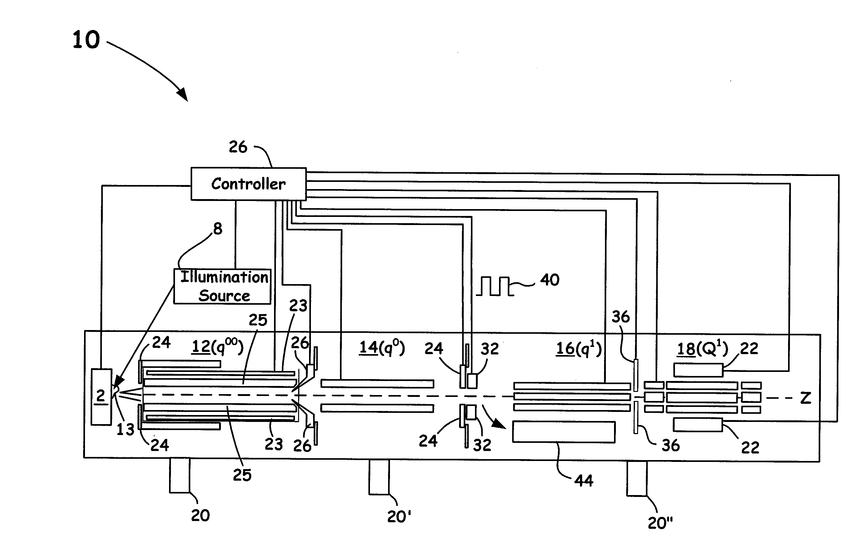
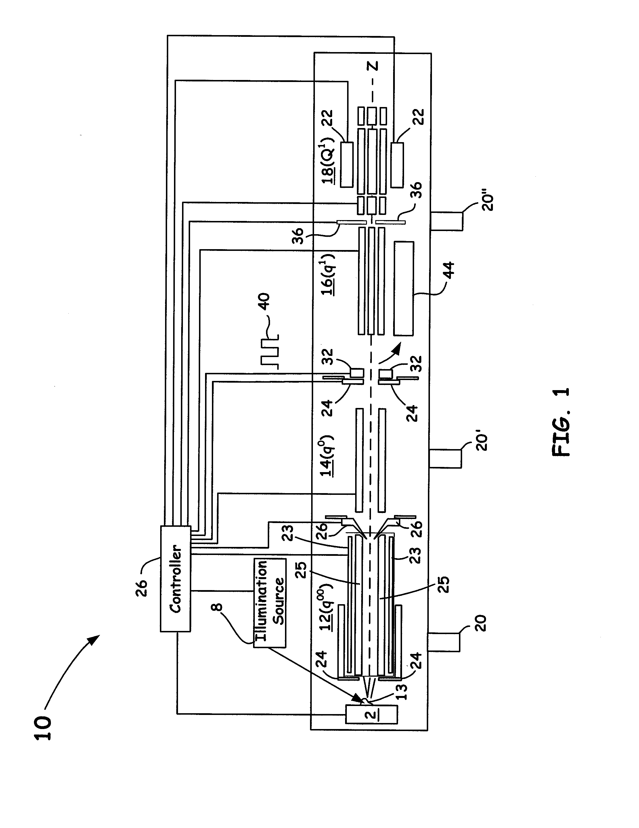
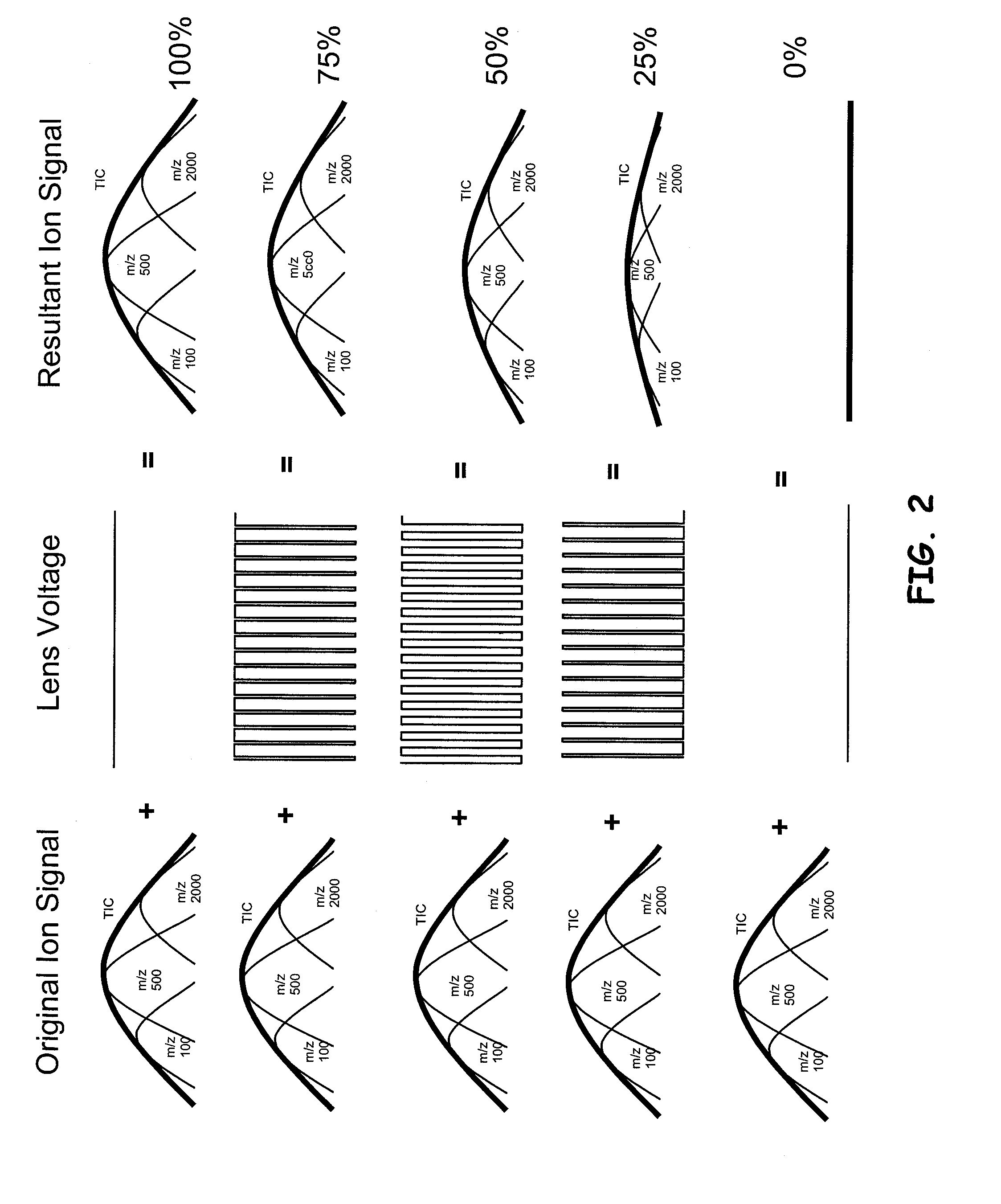
[0007]The present invention provides for techniques and configurations of protecting a mass spectrometer against sample over-loading, without sacrificing detection limits, with respect to detection of desired atoms or molecules embedded in a temporally non-uniform ion beam as produced from predetermined non-continuous ion source assemblies. In particular, a variable duty cycle is applied to one or more pulses of ions resultant from such an ion source, wherein the duty cycle is adjusted, often linearly adjusted based on a previous mass resolved scan, non-mass resolved or mass resolved pre-scan at duty cycle of greater than 0 up to about 100%. Such configurations and techniques, as disclosed herein, enable control of the total number of ions formed during the analysis itself.
[0009]Accordingly, in one aspect, the present invention is directed to a mass spectrometer that is configured to operate with a non-continuous ion source that generates one or more temporally non-uniform packets of ions and a means for gating such temporally non-uniform packets of ions at a frequency that results in a period that is substantially lower than the smallest non-uniformity period of the generated one or more temporally non-uniform packet of ions. Thereafter, a mass analyzer is configured to receive the temporally non-uniform packets of ions, wherein one or more received ions within the packets of ions are then released from the mass analyzer to be measured as well as to provide feedback control of the duty cycle so that saturation and space charge effects can be minimized in the instrument.
[0010]In another aspect, the present invention provides for a method of operating a non-continuous mass spectrometer configured so to provide for ion abundance control receive that includes: generating one or more temporally non-uniform packets of ions, gating the one or more temporally non-uniform packets of ions at a duty cycle determined by a received signal and having a frequency that results in a period that is substantially lower than the smallest non-uniformity period of the generated one or more temporally non-uniform packet of ions, providing feedback control of the duty cycle so that saturation and space charge effects can be minimized in the non-continuous mass spectrometer; and measuring the gated one or more temporally non-uniform packets of ions to provide for mass analysis.
[0012]The present invention is thus directed to a novel method and a mass spectrometer assembly that is beneficially configured with non-continuous sources, such as, for example, a Matrix Assisted Laser Desorption Ionization (MALDI) ion source, a Laser Desorption Ionization (LDI) ion source, and a Surface-Enhanced Laser Desorption / Ionization (SELDI) ion source. Accordingly, such configurations and methods disclosed herein enable the control of the number of ions to be detected from a non-continuous ion source that produces temporally non-uniform ion beams. Such configurations increases the dynamic range of configured detectors, reduces contamination of the system as a whole, while minimizing deleterious space charge effects.

Problems solved by technology

Thus, it is the duty cycle range that directly determines the dynamic range of the system and is limited by the desired dynamic range and limits of the electronics.

Method used


Image

  • Automatic gain control (AGC) method for an ion trap and a temporally non-uniform ion beam
  • Automatic gain control (AGC) method for an ion trap and a temporally non-uniform ion beam
  • Automatic gain control (AGC) method for an ion trap and a temporally non-uniform ion beam

Examples


Embodiment Construction

[0020]In the description of the invention herein, it is understood that a word appearing in the singular encompasses its plural counterpart, and a word appearing in the plural encompasses its singular counterpart, unless implicitly or explicitly understood or stated otherwise. Furthermore, it is understood that for any given component or embodiment described herein, any of the possible candidates or alternatives listed for that component may generally be used individually or in combination with one another, unless implicitly or explicitly understood or stated otherwise. Additionally, it will be understood that any list of such candidates or alternatives is merely illustrative, not limiting, unless implicitly or explicitly understood or stated otherwise.

[0021]Moreover, unless otherwise indicated, numbers expressing quantities of ingredients, constituents, reaction conditions and so forth used in the specification and claims are to be understood as being modified by the term “about.” ...


PUM


Abstract

An automatic gain control (AGC) technique and apparatus is introduced herein for any temporally non-uniform ion beam, such as, for example, an ion beam produced by a MALDI ion source so as to minimize space charge effects. The disclosed configurations and techniques can be achieved by using an ion optical gating element and applying a desired signal waveform (e.g., a square wave) having a predetermined duty cycle. The applied voltage amplitude of such a signal can be configured to switch between a voltage which fully transmits the ions, and a voltage which does not transmit any ions. The frequency is chosen to result in a period which is significantly lower than the smallest non-uniformity period. Techniques of the present invention can also be extended to methods of AGC which can use a single ion injection event from the ion source to avoid variations in ion numbers from an unstable ion source.

Description

BACKGROUND OF THE INVENTION[0001]1. Field of the Invention[0002]The present invention relates to the field of mass spectrometry, and more particularly to the field of automatic gain control in mass spectrometry to avoid saturation and / or space charge effects.[0003]2. Discussion of the Related Art[0004]Automatic gain control (AGC) is a method of controlling the number of ions in an ion trap to avoid saturation and / or space charge effects. Conventionally, AGC includes first injecting ions into the ion trap for some predetermined time using some gating optical element, typically in a pre-scan. A measurement of the resultant signal in the pre-scan is taken, and a calculation is then performed to determine what injection time (i.e. how long the gate is open) is needed to yield a specified “target” amount of signal, the target being the optimum signal which avoids saturation or space charge effects in the trap. The calculation often uses a simple linear relationship between ion signal and...

Claims


Application Information

Patent Timeline
Patent Type & Authority Applications(United States)
IPC IPC(8): H01J49/26
CPCH01J49/4265H01J49/061
Inventor SCHWARTZ, JAE C.KOVTOUN, VIATCHESLAV V.
Owner THERMO FINNIGAN
Learn More