Electric driver unit

a technology of electric driver, which is applied in the direction of machines/engines, mechanical equipment, output power, etc., can solve the problems of heat generation, mosfet may be damaged by heat, and mosfet may generate heat, so as to suppress the decrease in response performance of the electric valve timing adjusting apparatus, the effect of reducing the difficulty

Inactive Publication Date: 2010-01-28
DENSO CORP
View PDF10 Cites 7 Cited by
  • Summary
  • Abstract
  • Description
  • Claims
  • Application Information

AI Technical Summary

Benefits of technology

[0010]In view of the above and other difficulties, it is an objective of the present invention to provide an electric driver unit for an electric valve timing adjusting apparatus, the electric driver unit being capable of minimizing a difficulty associated with heat generation, and capable of suppressing a decrease in response performance of the electric valve timing adjusting apparatus, the decrease in response performance being related to temperature of oil that surrounds the electric valve timing adjusting apparatus.
[0012]According to the above electric driver unit, it is possible to minimize a difficulty associated with heat generation, and it is possible to suppress a decrease in response performance of the electric valve timing adjusting apparatus, the decrease in response performance being related to the temperature of the oil surrounding the electric valve timing adjusting apparatus.

Problems solved by technology

However, a flow of a large current to a circuit can bring a problem associated with heat generation.
For example, since the circuit typically employs a MOSFET (metal-oxide-semiconductor field-effect transistor, which is one type of field effect transistors) as a switching element for switching voltage application direction, there arises a difficulty that the MOSFET generates a heat and the MOSFET may be damaged by the heat.
When a circuit element operable at a large current is used, there arises another difficulty that a circuit board may increase in weight.
The inventors of the present application have however revealed that there is a difficulty in connection with the above described control of the drive current.
For example, the response performance of the electric valve timing adjusting apparatus is worsened when an engine is cool.
This is because the temperature of surrounding oil is a factor of worsening the response performance of the electric valve timing adjusting apparatus.

Method used


Image

  • Electric driver unit
  • Electric driver unit
  • Electric driver unit

Examples


Embodiment Construction

[0021]Exemplary embodiments are described below with reference to the accompanying drawings.

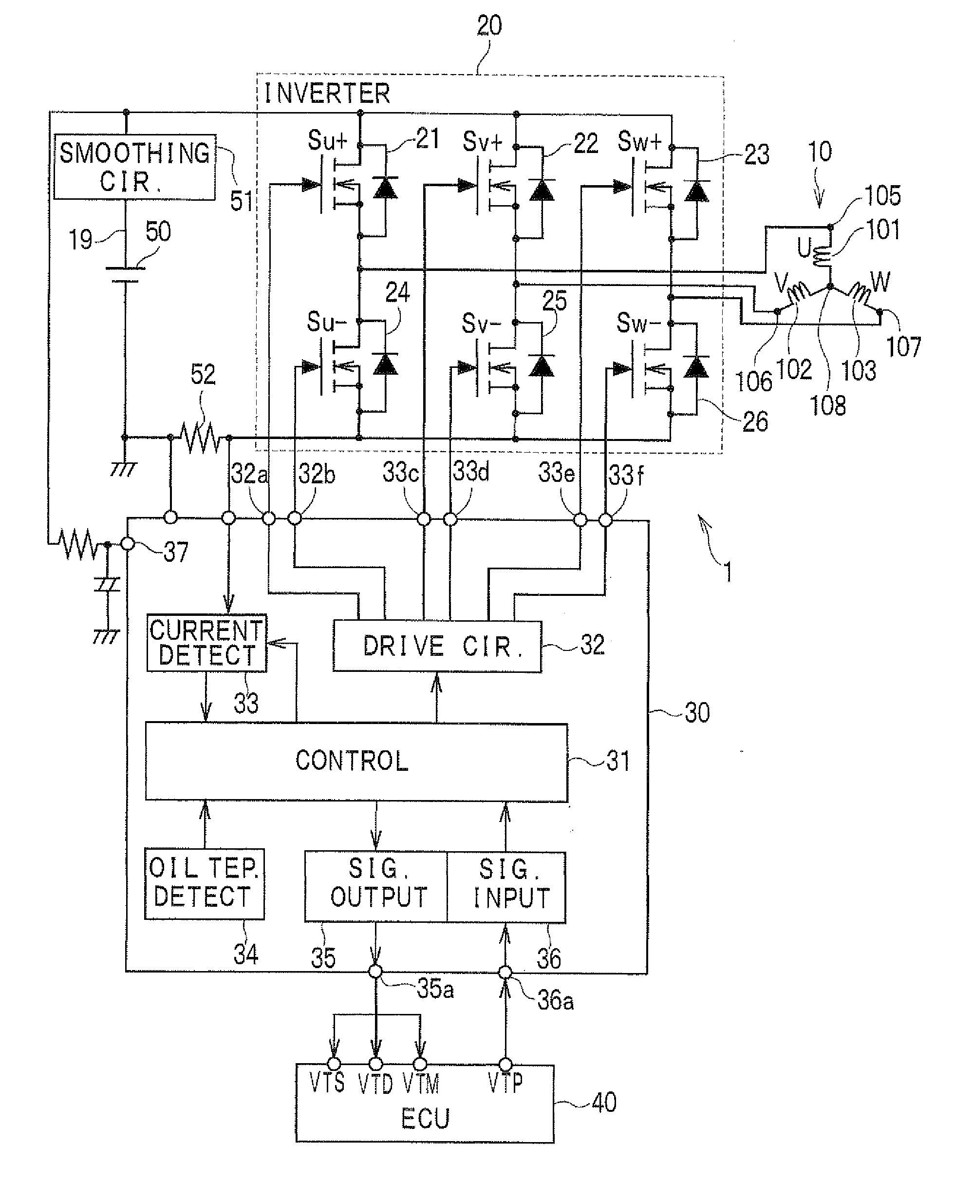
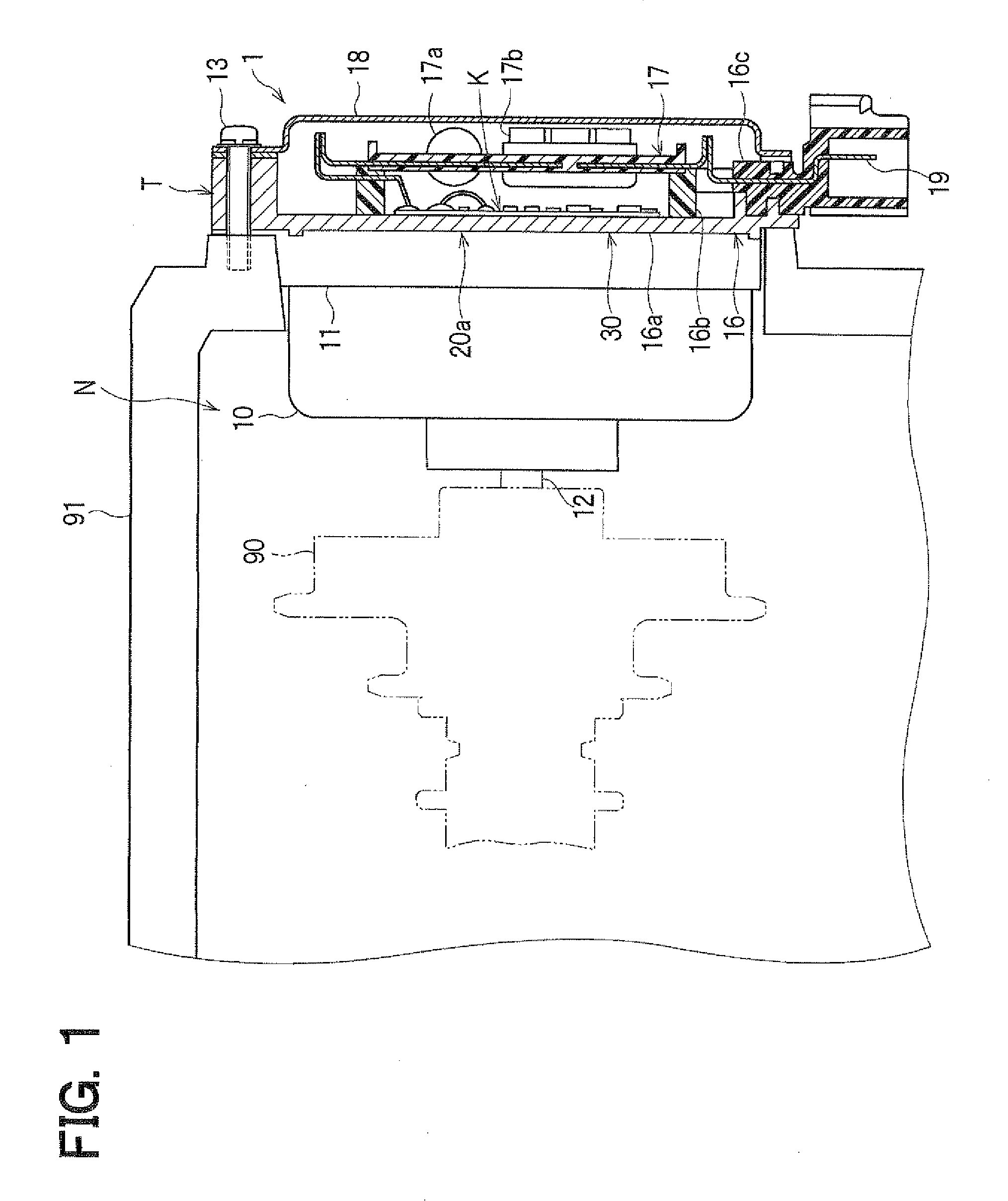
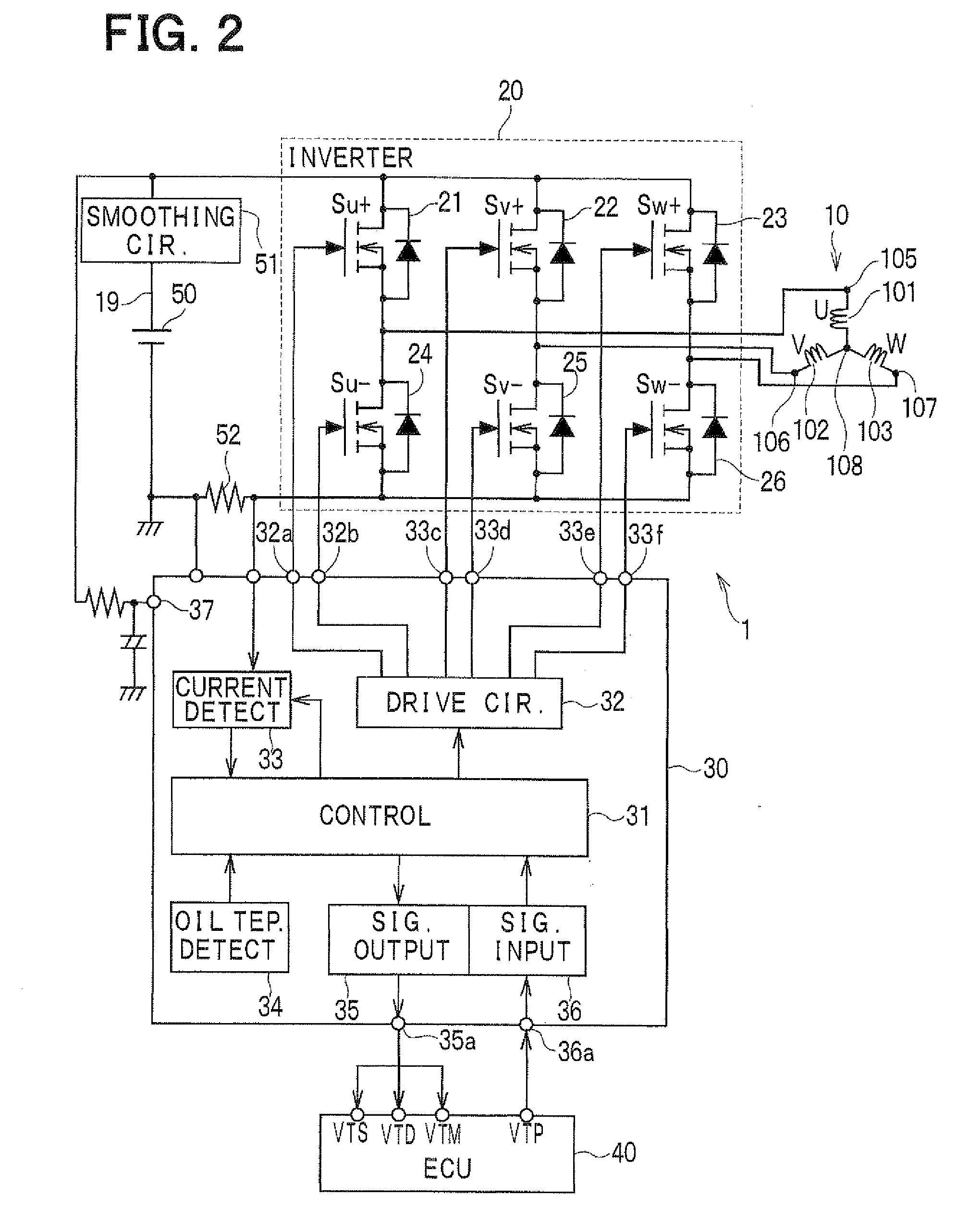
[0022]As shown in FIG. 1, an electric driver unit (EDU) 1 according to one embodiment includes an electric motor 10 for an electric valve timing adjusting apparatus 90 equipped in an engine of a vehicle. The EDU 1 drives and controls the electric motor 10, so that the electric valve timing adjusting apparatus 90 can adjust valve timing of opening and closing an inlet valve or an exhaust valve by utilizing rotary torque of the electric motor 10. In FIG. 1, the electric valve timing adjusting apparatus 90 is illustrated by using the dashed-two dotted line. For simplicity, the electric valve timing adjusting apparatus is also referred to herein as an adjusting apparatus.

[0023]The electric motor 10 is, for example, a three-phase brushless motor, and includes a motor case 11 and a motor axis 12. The motor case 11 is fixed to an engine head 91 by using a bolt 13. The motor axis 12 is supported by t...


PUM


Abstract

An electric driver unit for an electric valve timing adjusting apparatus is disclosed. The electric driver unit includes: a motor for driving the apparatus; a switching part for applying a drive voltage to the motor; a current information output part for providing current information associated with a current flowing in the switching part; a power distribution control part for controlling power distribution to the motor by controlling the switching part; and an oil temperature information output part for providing oil temperature corresponding value, which depends on temperature of oil that surrounds the apparatus. The power distribution control part controls the current based on the current information so that the current stays below a target value. The target value includes a normal value and a large value. The power distribution control part adopts the large value as the target value until the oil temperature corresponding value reaches a predetermined temperature.

Description

CROSS REFERENCE TO RELATED APPLICATION[0001]The present application is based on Japanese Patent Applications No. 2008-191805 filed on Jul. 25, 2008, disclosure of which is incorporated herein by reference.BACKGROUND OF THE INVENTION[0002]1. Field of the Invention[0003]The present invention relates to an electric driver unit for an electric valve timing adjusting apparatus that adjusts timing of opening and closing a valve of an internal combustion engine.[0004]2. Description of Related Art[0005]Internal combustion engines (referred to also as engine) for a vehicle are equipped with a valve timing adjusting apparatus, which adjusts timing of opening and closing a valve of the engine in accordance with a driving state of the engine. A valve timing adjusting apparatus adjusts a rotation phase of a camshaft relative to a crankshaft of the engine to an advanced angle or a retarded angle, and thereby changes the timing of opening and closing the valve in relation to rotation of the camsha...

Claims


Application Information

Patent Timeline
Patent Type & Authority Applications(United States)
IPC IPC(8): H02P7/285F01L1/34F01L1/356F02D13/02H02P6/06H02P6/08H02P6/28
CPCH02P7/285
Inventor MORINO, SEIJIKOZAWA, TAKAHARU
Owner DENSO CORP
Why Eureka
Try Eureka