Fuel cell emergency power system
a fuel cell and power system technology, applied in the direction of liquid degasification, cell components, separation processes, etc., can solve the problems of affecting the non-uniform membrane drying effect arising from this mechanism, and the inability to meet the requirements of the fuel cell, etc., to achieve the effect of reducing the risk of gas leakage, and reducing the efficiency of fuel cell power generation
- Summary
- Abstract
- Description
- Claims
- Application Information
AI Technical Summary
Problems solved by technology
Method used
Image
Examples
first embodiment
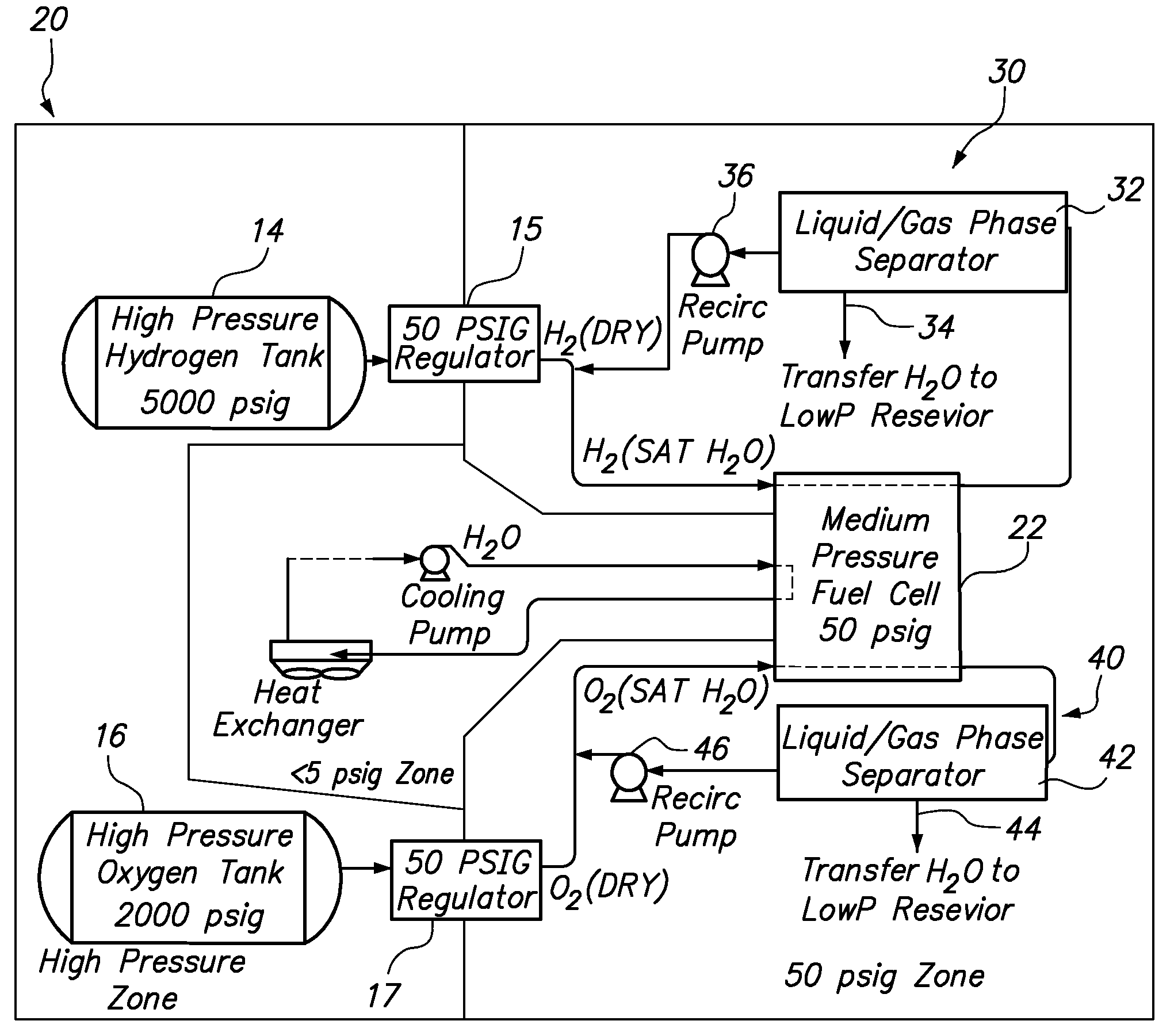
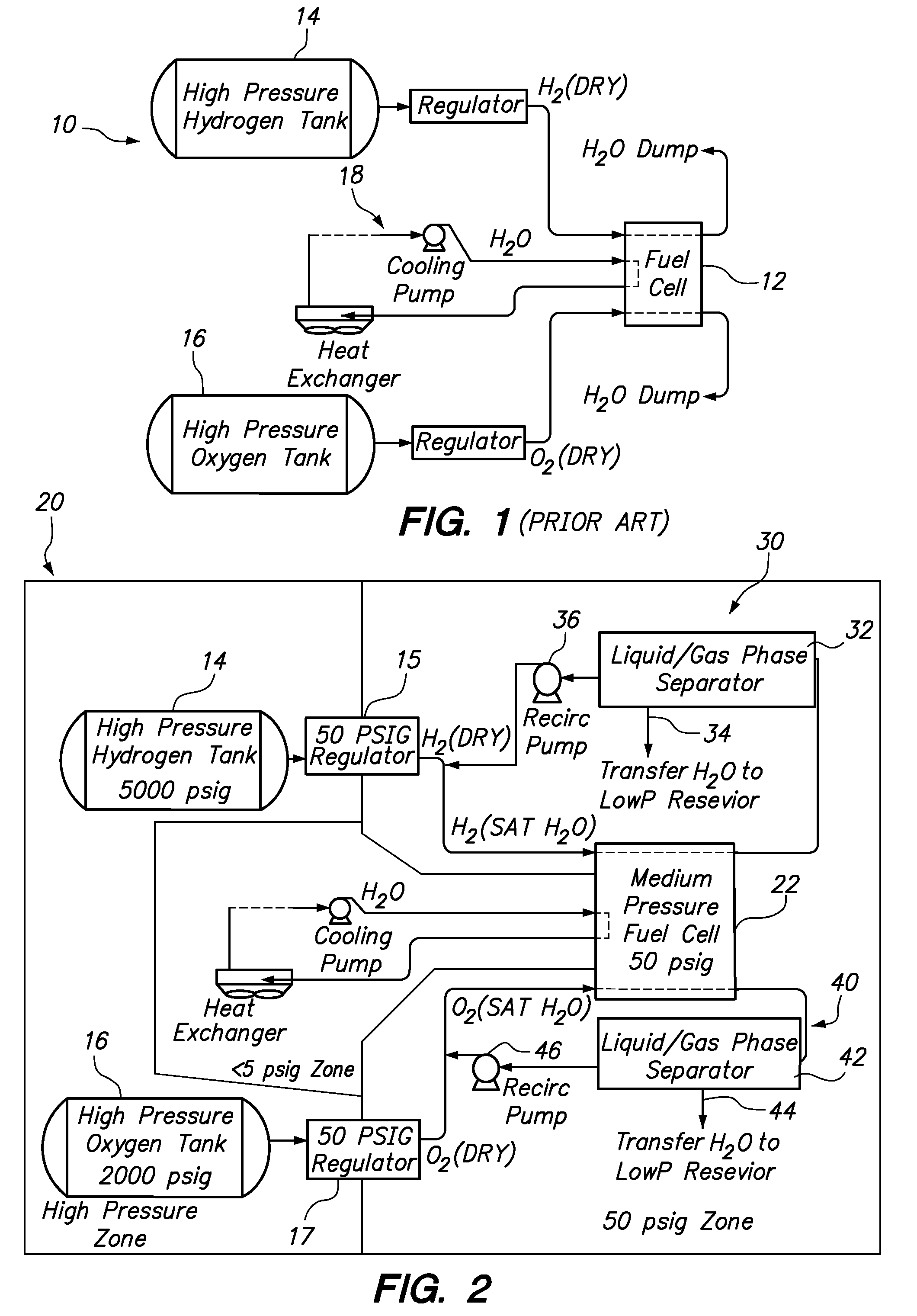
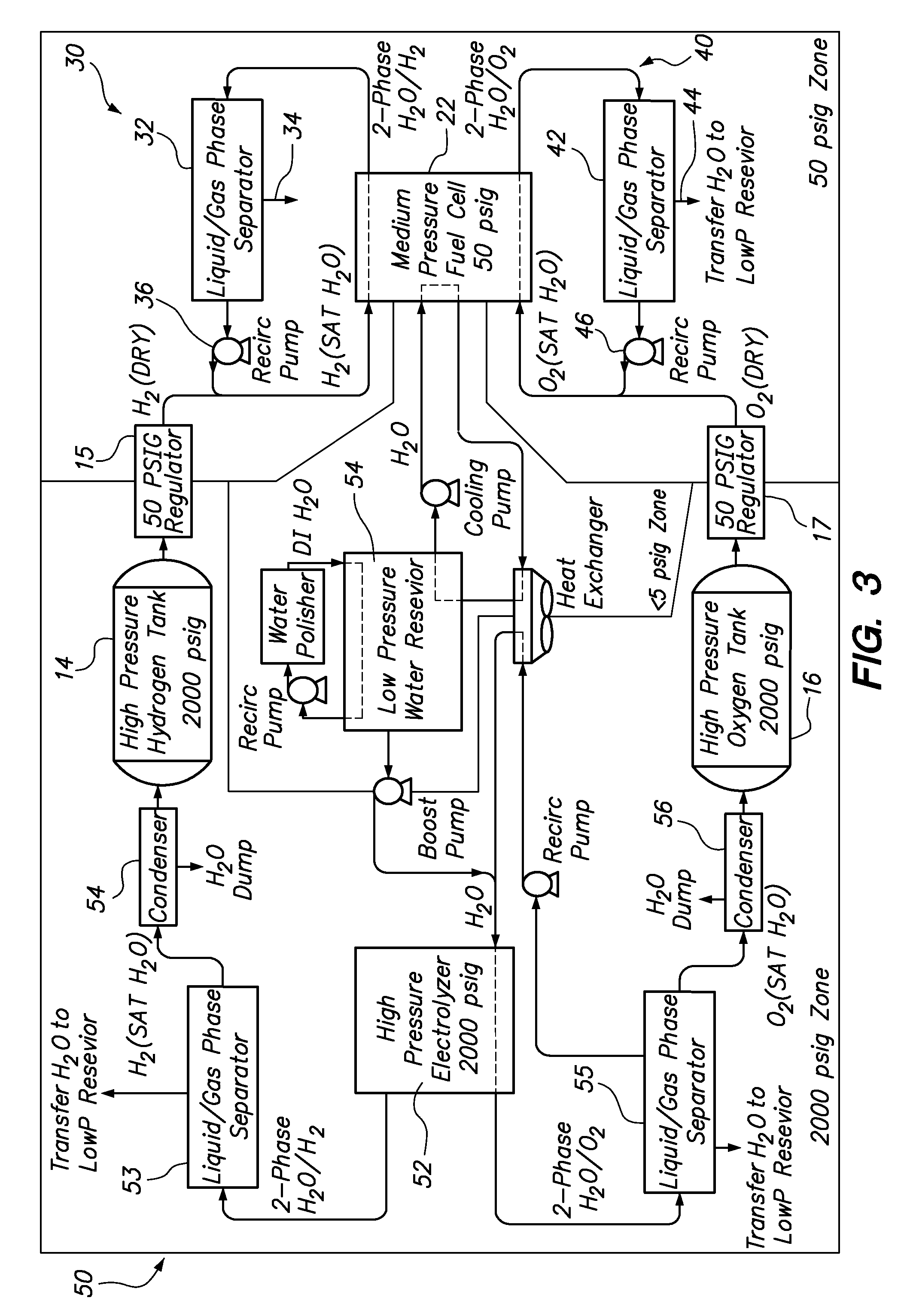
[0060]FIG. 4 is a schematic cross-sectional view of a liquid-gas phase separator 60 that is tolerant of highly turbulent conditions. The construction of the separator 60 may be used for any or all of the liquid-gas phase separators 32, 42, 53, 55 of FIGS. 2-3. However, the separators shown in FIGS. 4-8 will be described in terms of the oxygen-water separator 42 in the oxygen recirculation system 40 associated with the fuel cell 22. Still, it should be recognized that each of the separators having a mixed phase inlet conduit, a liquid outlet conduit, and a gas phase outlet conduit.
[0061]The gas phase separator 60 includes a closed, spherical vessel 62 where gas and liquid are allowed to separate. A first conduit 64 provides fluid communication from the cathodes of the fuel cell stack to the vessel 62 for gravity separation of a cathode outlet stream containing a liquid fraction and a gas fraction. A second conduit 66 provides fluid communication with the closed vessel 62 adjacent an ...
second embodiment
[0064]FIG. 5 is a schematic cross-sectional view of a liquid-gas phase separator 80 that is tolerant of highly turbulent conditions. The separator 80 is substantially similar to the separator 60 of FIG. 4, except for the addition of a baffle plate 83. The baffle plate 83 has a slight frustoconical shape (i.e., somewhat funnel-shaped) with a central opening 85 that allows water to fall through when the vessel 62 is oriented upright as shown in FIG. 5. A series of holes or gaps 87 are also provided through the baffle plate 83 around the perimeter of the plate, which gaps direct the accumulated water 65 around the side of the vessel 62 should be vessel become inverted.
third embodiment
[0065]FIG. 6 is a schematic cross-sectional view of a liquid-gas phase separator 90 that is tolerant of highly turbulent conditions. The separator 90 is substantially similar to the separator 80 of FIG. 5, except for the addition of a dip tube 92 at the central opening 85 of the baffle plate 83. The dip tube 92 reduces the amount of the accumulated water 65 that can flow directly toward the gas port 70 upon inversion of the vessel 62. Furthermore, the dip tube may provide an ideal location for a liquid level sensor.
PUM
| Property | Measurement | Unit |
|---|---|---|
| thicknesses | aaaaa | aaaaa |
| operating temperatures | aaaaa | aaaaa |
| electrical current | aaaaa | aaaaa |
Abstract
Description
Claims
Application Information
 - R&D
- Intellectual Property
- Life Sciences
- Materials
- Tech Scout
- Unparalleled Data Quality
- Higher Quality Content
- 60% Fewer Hallucinations
Browse by: Latest US Patents, China's latest patents, Technical Efficacy Thesaurus, Application Domain, Technology Topic, Popular Technical Reports.
© 2025 PatSnap. All rights reserved.Legal|Privacy policy|Modern Slavery Act Transparency Statement|Sitemap|About US| Contact US: help@patsnap.com


