Renewable electricity conversion of liquid fuels from hydrocarbon feedstocks

a technology of hydrocarbon feedstock and renewable electricity, which is applied in the direction of hydrogen/synthetic gas production, oxygen compound preparation by reduction, energy input, etc., can solve the problems of difficulty in adjusting electricity production to lack of substantial reduction in petroleum use of electricity, and difficulty in adjusting electricity production to meet the needs of electrical utilities

Active Publication Date: 2010-01-28
INENTEC
View PDF12 Cites 49 Cited by
  • Summary
  • Abstract
  • Description
  • Claims
  • Application Information

AI Technical Summary

Benefits of technology

[0013]The electricity from the renewable energy source may be used to power a plasma included in the synthesis gas generation unit, a joule heated melter included in the synthesis gas generation unit, or combinations thereof. At least a portion of the oxygen produced by the air separation unit may also be stored for use at a later time. While not meant to be limiting, the air separation unit is preferably provided as a cryogenic separation unit. Also while not meant to be limiting, the oxygen produced in the air separation unit is preferably stored cryogenically. Another advantage of the present invention is the capability to vary the relative amounts of plasma heating, melter heating, oxygen and steam provided in the synthesis gas generation unit in response to variations in the amount of renewable energy source electricity. While not meant to be limiting, it is preferred that the electricity to the joule heated melter included in the synthesis gas generation unit is reduced at disproportionately smaller amount when the electricity input from the renewable energy source to the synthesis gas generation unit is reduced. The present invention may also include embodiments where at least some of the electricity from the renewable energy source is provided to a transmission system for use by a downstream user.
[0014]Another embodiment of the present invention replaces the air separation unit with an electrolysis unit. In an embodiment that includes and electrolysis unit, at least a portion of the oxygen produced in the electrolysis unit may be saved for use at a later time, and oxygen produced in the electrolysis unit may stored cryogenically. When utilizing an electrolysis unit, the present invention may produce liquid fuel by reacting CO2 generated from the hydrocarbon feedstock with hydrogen produced in the electrolysis unit. In this type of arrangement, some of the renewable energy source electricity may be used for compressing CO2.

Problems solved by technology

This makes it difficult to match the electricity production to the needs of the electrical utilities that consume it.
A further issue is that electricity does not provide a means to make a substantial reduction in petroleum use in the near term since it cannot be used to directly replace petroleum use in present cars and trucks.
However, these approaches have substantial cost and scale issues, and are limited in location.
None of these approaches provide easily substituted fuels for petroleum based transportation fuels.
There are problems with distribution, storage, use of hydrogen that in most cases are not acknowledged by the authors, and the common usage of electrolysis releases the oxygen generated in the process rather than utilizing it in a beneficial way.

Method used


Image

  • Renewable electricity conversion of liquid fuels from hydrocarbon feedstocks
  • Renewable electricity conversion of liquid fuels from hydrocarbon feedstocks
  • Renewable electricity conversion of liquid fuels from hydrocarbon feedstocks

Examples


Embodiment Construction

[0024]For the purposes of promoting an understanding of the principles of the invention, reference will now be made to the embodiments illustrated in the drawings and specific language will be used to describe the same. It will nevertheless be understood that no limitations of the inventive scope is thereby intended, as the scope of this invention should be evaluated with reference to the claims appended hereto. Alterations and further modifications in the illustrated devices, and such further applications of the principles of the invention as illustrated herein are contemplated as would normally occur to one skilled in the art to which the invention relates.

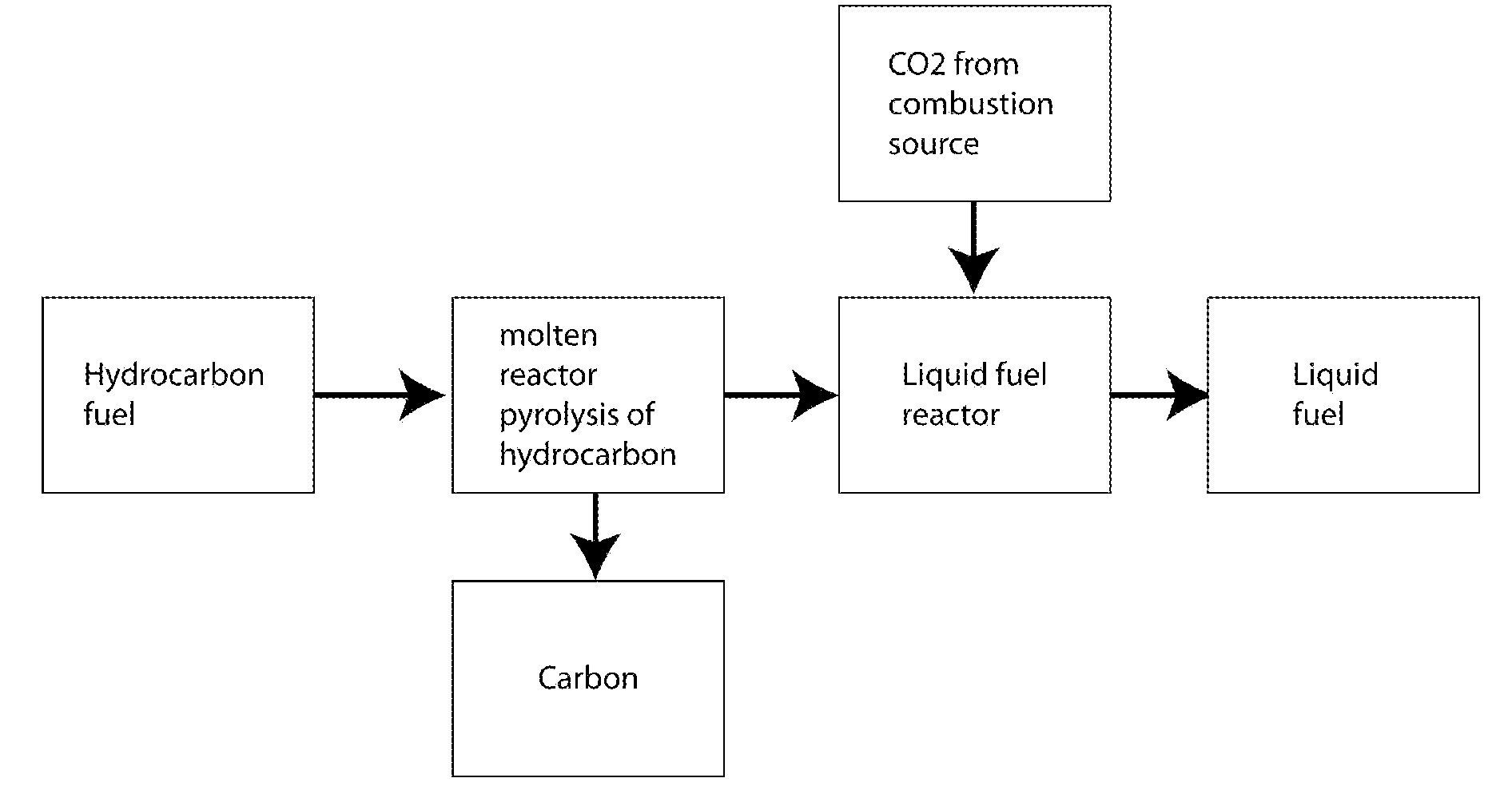
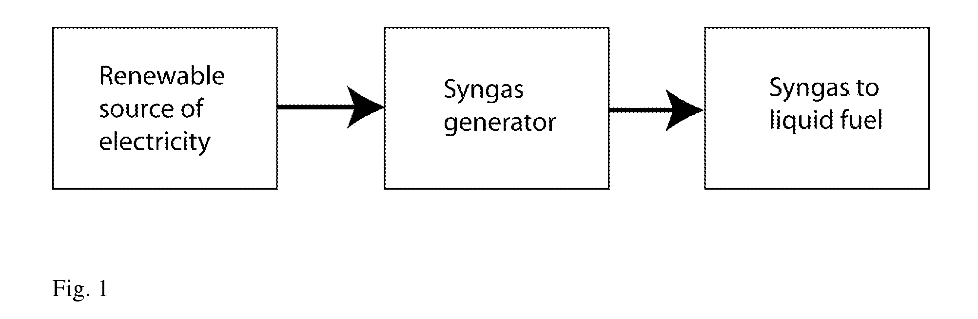
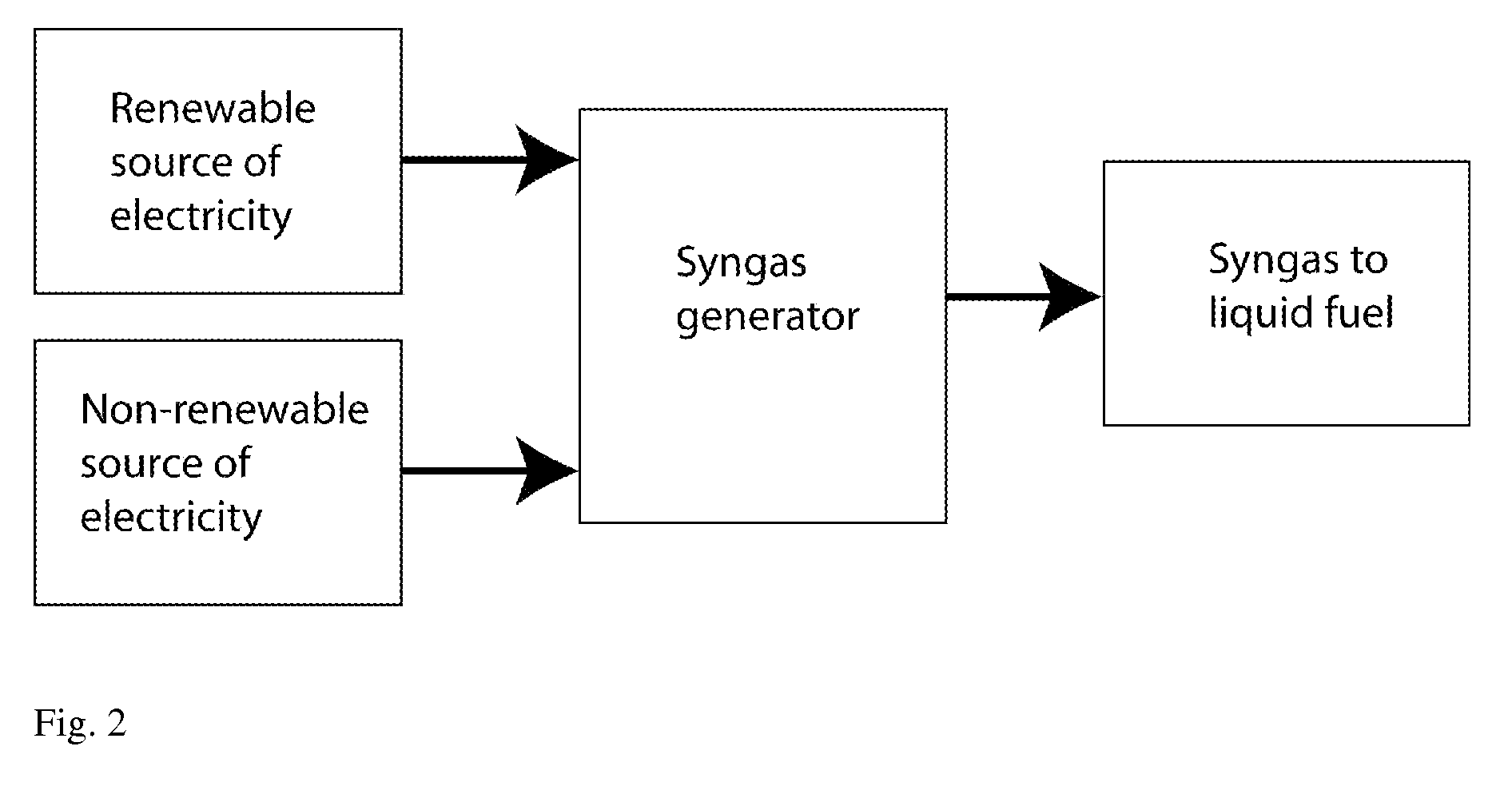
[0025]It is the purpose of this invention to provide systems for improved use of electricity from renewable energy sources, such as wind or solar energy, through the conversion of hydrocarbon feedstocks into a liquid fuel. The feedstocks include municipal and industrial waste, biomass, coal and natural gas. These systems can bot...


PUM

PropertyMeasurementUnit
timeaaaaaaaaaa
renewable electrical energyaaaaaaaaaa
flexibilityaaaaaaaaaa

Abstract

The present invention includes a method for converting renewable energy source electricity and a hydrocarbon feedstock into a liquid fuel by providing a source of renewable electrical energy in communication with a synthesis gas generation unit and an air separation unit. Oxygen from the air separation unit and a hydrocarbon feedstock is provided to the synthesis gas generation unit, thereby causing partial oxidation reactions in the synthesis gas generation unit in a process that converts the hydrocarbon feedstock into synthesis gas. The synthesis gas is then converted into a liquid fuel.

Description

CROSS REFERENCE TO RELATED APPLICATIONS[0001]This application is a Continuation in Part of U.S. Ser. No. 11 / 177,152, filed Jul. 6, 2005, for METHOD FOR ENHANCING THE OPERATION OF ELECTRICAL POWER PLANTS AND ENERGY STORAGE now U.S. Pat. No. ______, the entire contents of which are incorporated herein by this reference. This application further claims priority to U.S. Provisional Application Ser. No. 61 / 103,397, filed Oct. 7, 2008, entitled “Renewable Electricity Conversion of Liquid Fuels From Hydrocarbon Feedstocks” and U.S. Provisional Application Ser. No. 61 / 107,563, filed Oct. 22, 2008, entitled “Renewable Electricity Conversion of Liquid Fuels From Hydrocarbon Feedstocks-2” the entire contents of each of which are incorporated herein by this reference.TECHNICAL FIELD[0002]This invention relates to a system for optimal use of variable electricity from a renewable energy source, such as from wind and solar, in the production of liquid fuels from various hydrocarbon feedstocks, and...

Claims


Application Information

Patent Timeline
Patent Type & Authority Applications(United States)
IPC IPC(8): C07C1/04F25J3/00
CPCC01B3/24C10G2/00C01B2203/0833C01B2203/085C01B2203/0861C01B2203/0866C01B2203/1241C01B2203/84C01B2203/86C10G2/32C10J3/00C10J2300/0916C10J2300/093C10J2300/0946C10J2300/0959C10J2300/1284C10J2300/1659C10J2300/1684C10J2300/1846F23G5/46F23G2206/203Y02E20/12Y02E50/32C10G2400/02C10G2400/04C10G2400/08Y02E50/13C01B3/36C07C29/15C01B2203/0272Y02P20/145Y02P20/133Y02P20/582Y02T50/678Y02E50/10Y02E50/30Y02P30/00C01B13/0229C01B2203/0216C01B2203/0255C01B2203/06C01B2203/061C01B2203/1235C01B2203/82C07C29/151C10J3/82C10J2300/1665
Inventor COHN, DANIEL R.SURMA, JEFFREY E.BROMBERG, LESLIE
Owner INENTEC
Why Eureka
Try Eureka