Resilient arthroplasty device

a technology of arthroplasty and splint, applied in the field of implants, can solve the problems of fracture, joint space loss, ankle joint replacement, etc., and achieve the effects of reducing pain and dysfunction, improving physiologic motion and shock absorption, and preserving joint motion

Active Publication Date: 2010-01-28
IORTHOPEDICS INC
View PDF29 Cites 95 Cited by
  • Summary
  • Abstract
  • Description
  • Claims
  • Application Information

AI Technical Summary

Benefits of technology

[0004]The present invention is directed to an orthopedic implant configured for deployment between opposing members of a joint structure that addresses many of the shortcomings of prior artificial joints. The arthroplasty implants embodying features of the invention are configured to preserve joint motions while removing the pain and dysfunction following the development of arthritis or joint injury. The arthroplasty implant in accordance with the present invention achieves improved physiologic motion and shock absorption during gait and acts as a resilient spacer between moving bones during limb movement. The combined characteristics of the implant include anatomic design symmetry, balanced rigidity with variable attachment connections to at least one of adjacent normal structures, and durability which addresses and meets the needs for repair or reconstruction thus far missed in the prior art. The implant should be secured to at least one of the bones of the joint structure.

Problems solved by technology

When hyaline articular cartilage is damaged, it breaks down and joint space is lost.
Current arthroplasty techniques typically use “plastic and metal” implants that are rigid and which ultimately fail due to loosening or infection.
Ankle joint replacements, on the other hand, are not very successful, and often fail in the first several years after surgery.

Method used


Image

  • Resilient arthroplasty device
  • Resilient arthroplasty device
  • Resilient arthroplasty device

Examples


Embodiment Construction

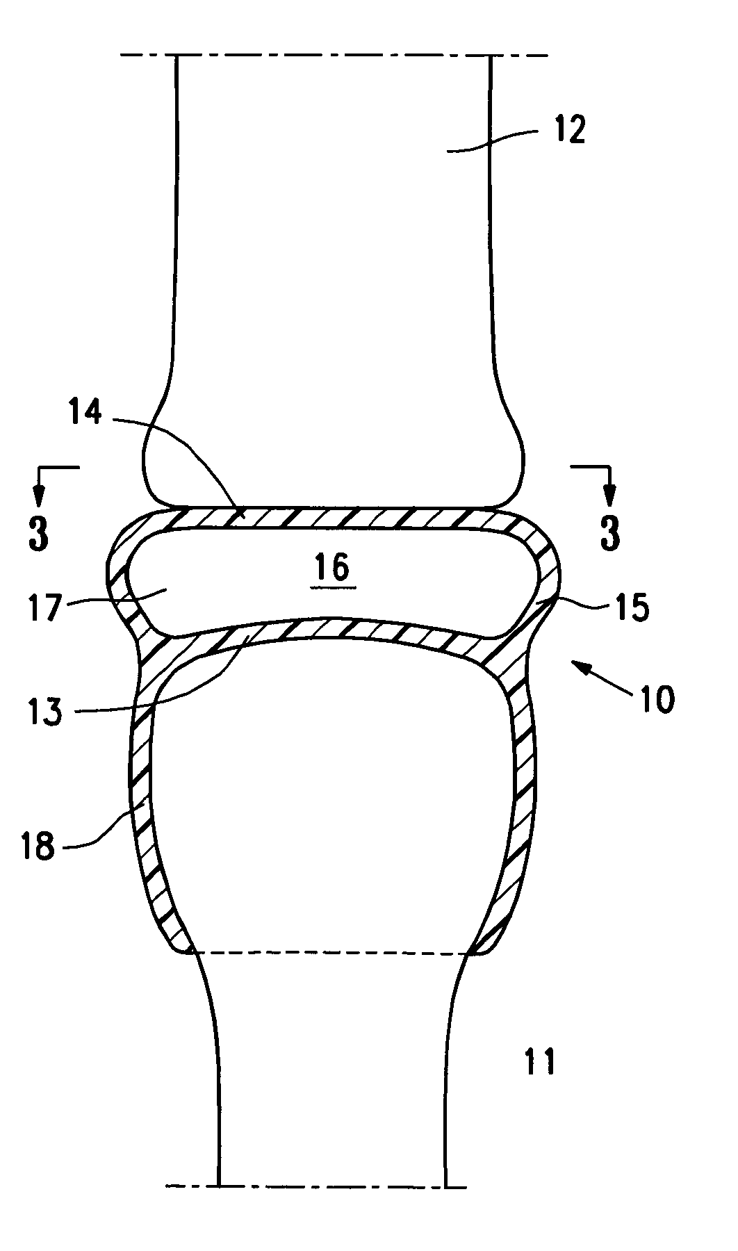
[0025]The present invention is directed to arthroplasty implants and procedures for a wide variety of joints such as, for example, hips, knees, shoulders, ankles, elbows, wrists, fingers, toes, temporomandibular joints and the like, but for clarity, as well as brevity, the discussion herein will focus on an implant for a hip joint and an implant for replacing the talus bone of a patient's ankle.

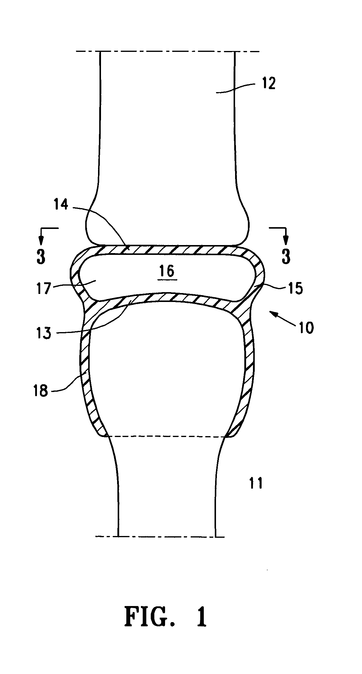
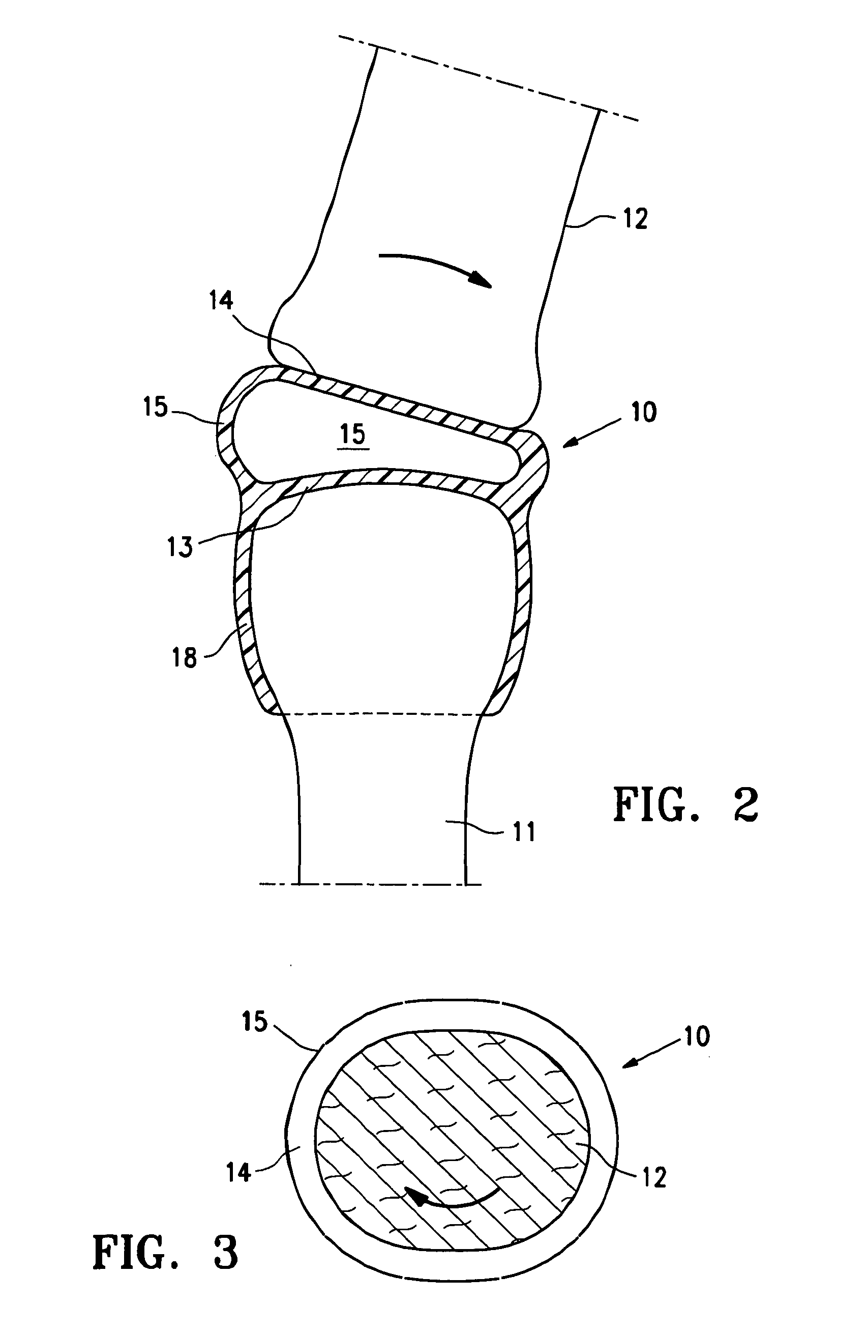
[0026]FIG. 1 is a highly schematic idealized view of an implant 10 embodying features of the invention that is deployed within a joint structure having a first bone 11 and a second bone 12. The implant 10 has a first wall 13, a second wall 14, and a side wall 15 which define the implant interior 16 which contains filling material 17. The first wall 13 is secured to the end of the first bone 11 by the skirt 18 that extends from the first wall 13 and the second wall 14 engages the end surface of the second bone 12 and may also be secured thereto. The side wall 15 extending between the first and...


PUM


Abstract

The disclosure is directed to a resilient implant for implantation into human or animal joints to act as a cushion allowing for renewed joint motion. The implant endures variable joint forces and cyclic loads while reducing pain and improving function after injury or disease to repair, reconstruct, and regenerate joint integrity. The implant is deployed in a prepared debrided joint space, secured to at least one of the joint bones and expanded in the space, molding to surrounding structures with sufficient stability to avoid extrusion or dislocation. The implant has opposing walls that move in varied directions, and an inner space filled with suitable filler to accommodate motions which mimic or approximate normal joint motion. The implant pads the damaged joint surfaces, restores cushioning immediately and may be employed to restore cartilage to normal by delivering regenerative cells.

Description

RELATED APPLICATIONS[0001]This application is related to provisional application Ser. No. 61 / 135,820, filed on Jul. 24, 2008, which is incorporated herein in its entirety and which is relied upon for priority.BACKGROUND OF THE INVENTION[0002]This invention relates to arthroplasty, and more particularly, to an implant for use in arthroplasty. When hyaline articular cartilage is damaged, it breaks down and joint space is lost. Inflammatory enzymes such as from the Cox-1, Cox-2 and / or 5-Lox systems, are released and loose bodies form adding to the degradation of joint function. Such joint damage is conventionally treated by physical therapy, analgesics, pain medication and injections. When these treatments fail, the traditionally accepted treatment option is arthroplasty implantation or replacing the joint with an artificial joint construct. Current arthroplasty techniques typically use “plastic and metal” implants that are rigid and which ultimately fail due to loosening or infection....

Claims


Application Information

Patent Timeline
Patent Type & Authority Applications(United States)
IPC IPC(8): A61F2/08
CPCA61B17/842A61F2002/4212A61F2/30756A61F2/32A61F2/38A61F2/3872A61F2/389A61F2/40A61F2/4202A61F2002/30563A61F2002/30576A61F2002/30581A61F2002/30594A61F2002/30688A61F2002/30754A61F2002/30757A61F2/30721A61B17/562A61F2/3603A61F2002/30019A61F2002/30589A61F2250/0048
Inventor GROTZ, R. THOMAS
Owner IORTHOPEDICS INC
Why Eureka
Try Eureka