Filter for removing a sulfur-containing-gas and method for removing a sulfur-containing-gas using the same

a technology for filtering and sulfur-containing gas, which is applied in the direction of filtration separation, electrochemical generators, and separation processes, etc., can solve the problems that the conventional materials for removing sulfur-containing gas as described in documents 1 and 2 do not necessarily have cannot be demonstrated for a long period of time sufficient sulfur-containing-gas removal performance, etc., to achieve high sulfur-containing-gas removal performance, high removal performance, and fast adsorption rate ratio ratio

Inactive Publication Date: 2010-02-04
TOYOTA BOSHOKU KK
View PDF12 Cites 15 Cited by
  • Summary
  • Abstract
  • Description
  • Claims
  • Application Information

AI Technical Summary

Benefits of technology

[0017]Meanwhile, the latter filter according to the present invention comprises the activated carbon fiber with the alkali component supported thereon. Such an activated carbon fiber has neither macropores nor mesopores, and thus the adsorption rates of sulfur-containing-gas thereto are fast. For this reason, in the present invention, a trace amount of sulfur-containing-gas which ooze out from the former filter can be adsorbed to the latter filter. Accordingly, extremely high sulfur-containing-gas removal performance is exhibited. The present inventors speculate that, since the filter for removing a sulfur-containing-gas of the present invention comprises the former filter and the latter filter as described abov

Problems solved by technology

However, conventional materials for removing a sulfur-containing-gas as described in Documents 1 and 2 do not necessarily have sufficient sulfur-containing-gas removal performance.

Method used


Image

  • Filter for removing a sulfur-containing-gas and method for removing a sulfur-containing-gas using the same
  • Filter for removing a sulfur-containing-gas and method for removing a sulfur-containing-gas using the same
  • Filter for removing a sulfur-containing-gas and method for removing a sulfur-containing-gas using the same

Examples


example 1

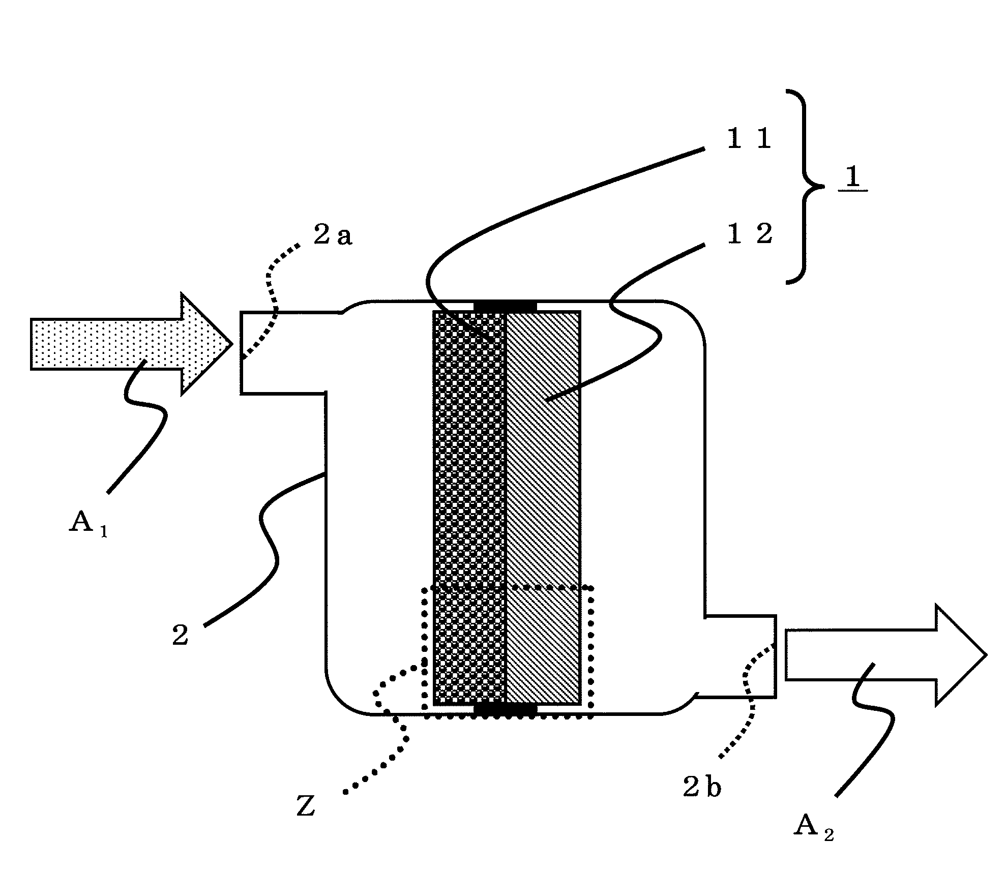
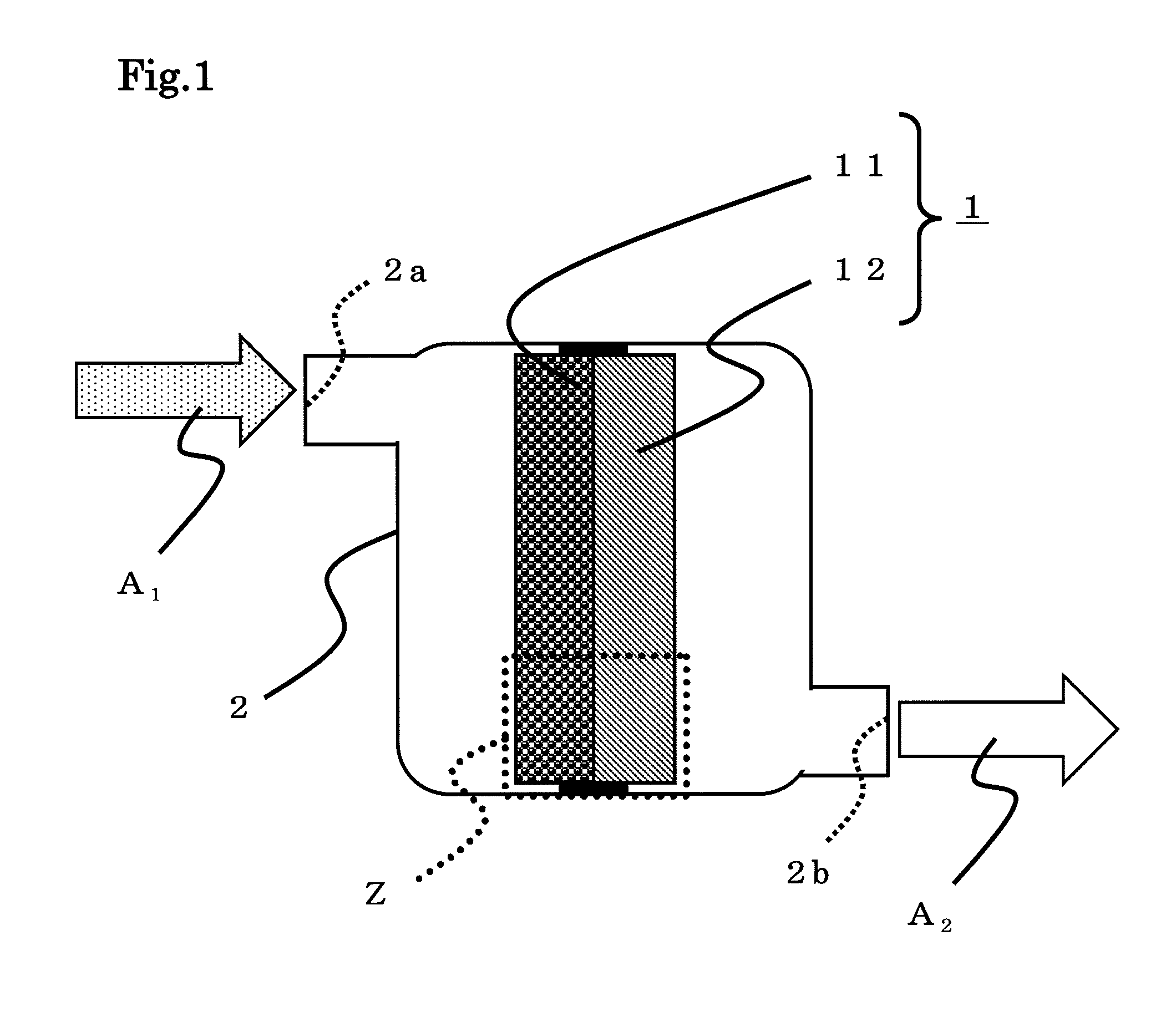
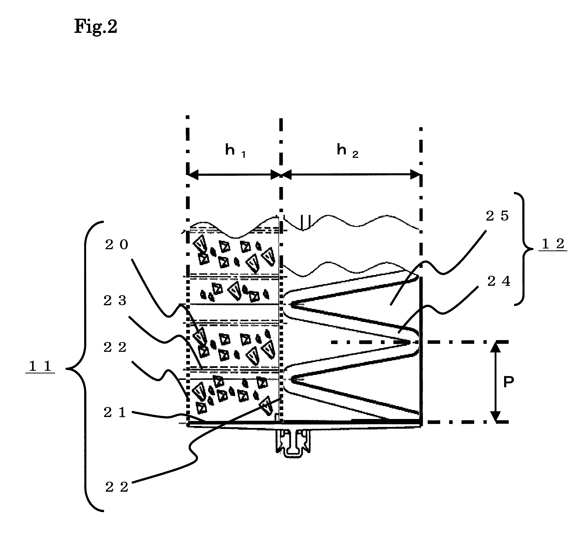
[0070]A filter for removing a sulfur-containing-gas having the above-described structure shown in FIG. 1 and FIG. 2 was produced. Note that a former filter and a latter filter had the following structures.

[0071][Former Filter 11]

The amount of a first material for removing a sulfur-containing-gas (activated carbon supporting iodine) used: 600 g

The particle diameter of the first material for removing a sulfur-containing-gas: 2.8 to 4.7 mm (6.5 to 4 mesh) Filter dimensions: 200 mm in length, 200 mm in width, and 30 mm in height (h1)

Mesh Member 22: PTFE (polytetrafluoroethylene), 100 mesh

[0072][Latter Filter 12]

A second material for removing a sulfur-containing-gas (potassium carbonate-attached activated carbon fiber) Filter dimensions: 200 mm in length, 200 mm in width, 50 mm in folded width (h2), and 24 mm in pitch (P).

[0073]In addition, the first material for removing a sulfur-containing-gas was produced as follows. Specifically, first, an ammonium iodide aqueous solution was prepare...


PUM

PropertyMeasurementUnit
Fractionaaaaaaaaaa
Fractionaaaaaaaaaa
Percent by massaaaaaaaaaa

Abstract

Provided is a filter for removing a sulfur-containing-gas (1), which removes the sulfur-containing-gas by being brought into contact with the sulfur-containing-gas in a gas flow path, the filter comprising a former filter (11) disposed on an upstream side of the gas flow path, and a latter filter (12) disposed on a downstream side of the gas flow path, wherein
    • the former filter (11) comprises a first material for removing a sulfur-containing-gas, the first material comprising a porous support, and iodine which is supported on the porous support, and is produced by catalytic pyrolysis of ammonium iodide at a thermal decomposition ratio of 80% or more by use of the porous support as a catalyst, and
    • the latter filter (12) comprises a second material for removing a sulfur-containing-gas, the second material comprising an activated carbon fiber, and an alkali component which is supported on the activated carbon fiber.

Description

TECHNICAL FIELD[0001]The present invention relates to a filter for removing a sulfur-containing-gas and a method for removing a sulfur-containing-gas using the same, and more specifically relates to: a filter for removing a sulfur-containing-gas which removes a sulfur-containing-gas by being brought into contact with the sulfur-containing-gas; and a method for removing a sulfur-containing-gas using the same.BACKGROUND OF THE INVENTION[0002]Conventionally, activated carbons have been utilized to remove harmful gases. In recent years, in order to further improve the gas removing capabilities of such activated carbons, various materials for removing a sulfur-containing-gas, in which attached substances such as metal compounds and halogen compounds are supported on activated carbons, have been disclosed.[0003]For example, Japanese Unexamined Patent Application Publication No. Hei 11-347398 (Document 1) discloses an material for removing a acidic-gas in which 10 to 30 parts by mass of an...

Claims


Application Information

Patent Timeline
IPC IPC(8): B01D53/14B01D50/00B01D53/48
CPCB01D53/508B01D53/8615B01D2251/30Y02E60/50H01M8/0675H01M8/0687B01D2255/702
Inventor FUKUMOTO, KAZUHIROTAKAHARA, MINORUSUZUKI, KENICHIROUNAKAGAKI, NOBUHIKOARAI, YASUNARIHONDA, MINORU
Owner TOYOTA BOSHOKU KK
Why Eureka
Try Eureka