Illumination apparatus for conducting and dissipating heat from a light source

a technology of light source and heat dissipation apparatus, which is applied in the direction of lighting and heating apparatus, semiconductor devices for light sources, and light support devices. it can solve the problems of large lag time, large heat dissipation area, and large heat dissipation area, and achieve the effect of facilitating heat conduction

Inactive Publication Date: 2010-02-04
LIGHTING SCI GROUP
View PDF23 Cites 81 Cited by
  • Summary
  • Abstract
  • Description
  • Claims
  • Application Information

AI Technical Summary

Benefits of technology

[0020]The present invention solves the afore-mentioned problems in the art by providing an optics module having a pendant body composed of heat conductive material in combination with disposing a driving circuit within the proximal base portion of the optics module. In one such embodiment, the driving circuit may be disposed within a male threaded base at the proximal end of the optics module. Such a location of the driving circuit provides for protection of the driving circuit as well as facilitating the conduction of heat generated by the driving circuit to an independent heat dissipating element. In one embodiment, the heat dissipating element may comprise a heat sink independent of the optics module, into which the optics module may be releasably secured.

Problems solved by technology

The main problem with the standard light bulbs having resistive heating elements (e.g. tungsten) is that such a light source expends more energy as heat than as light.
Fluorescent lamps run substantially cooler, but have a substantial lag time between when they are initially turned on and when they actually start emitting light, and are often fairly bulky.
Halogen lamps are highly efficient, but need to be handled very carefully and generate a considerable amount of heat when manufactured large enough to provide a usable amount of light, even when powered with low voltage (e.g. 12V).
In addition, LEDs may be very small and have an extremely long service life, mainly due to the fact that they operate at cooler temperatures.
One current drawback with such LED lamps is that when used to replace a conventional incandescent bulb they must have special driving circuits that convert the incoming alternating-current line voltage to the direct-current low voltage needed by the lamp.
The problem with such a construction is that the driving circuit itself generates heat, particularly when the LED requires some meaningful amperage, albeit at low voltage.
Unfortunately the efficiency of an LED falls off rapidly as it gets hot, and thus known LED lamps tend to dim somewhat after they have been in use for a while and their driving circuits have gotten warm.
Such light emitting LED lamps cannot typically operate under normal conditions and tend to have high failure rates.
Typical problems caused by heating of the semiconductor junction and surrounding structure are: 1) failures brought on by such occurrences as non-homogenous distribution of the current density over the junction (“current crowding”), which causes a local hot spot in the diode junction leading to early failure due to thermal runaway; 2) nucleation and growth of dislocations in the active region of the diode in which the radiative recombination occurs due to the existence of an existing defect in the semiconductor crystalline structure and which is accelerated by heat; 3) degradation of materials utilized in the LED, such as phosphor, causing loss of efficiency and changes in output color; and 4) electromigration of metal atoms at the metallization layers of the diode causing growth of conductive “whiskers” and early failure.
An LED may be attached to a heat sink via heat conductive adhesive, but if the LED stops working, then the entire component must be discarded, making parts replacement costly.
Such LEDs are not exchangeable or serviceable and are therefore rendered disposable and very inefficient.
No. 2006 / 0050514 are directed at attempts to better conduct heat away from an LED semiconductor junction within an LED lamp via incorporation of heat conductive material within the LED lamp, however, neither reference discloses a means or additional structure to dissipate heat from the socket of the disclosed LED lamps.
However, utilizing LED light sources in modern light sources gives rise to the significant challenge of removing the heat from the LED semiconductor junction and surrounding structures.

Method used


Image

  • Illumination apparatus for conducting and dissipating heat from a light source
  • Illumination apparatus for conducting and dissipating heat from a light source
  • Illumination apparatus for conducting and dissipating heat from a light source

Examples


Embodiment Construction

[0042]Although the following detailed description contains many specifics for the purposes of illustration, anyone of ordinary skill in the art will appreciate that many variations and alterations to the following details are within the scope of the invention. Accordingly, the following preferred embodiments of the invention are set forth without any loss of generality to, and without imposing limitations upon, the claimed invention.

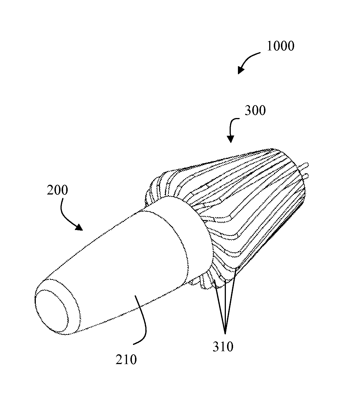
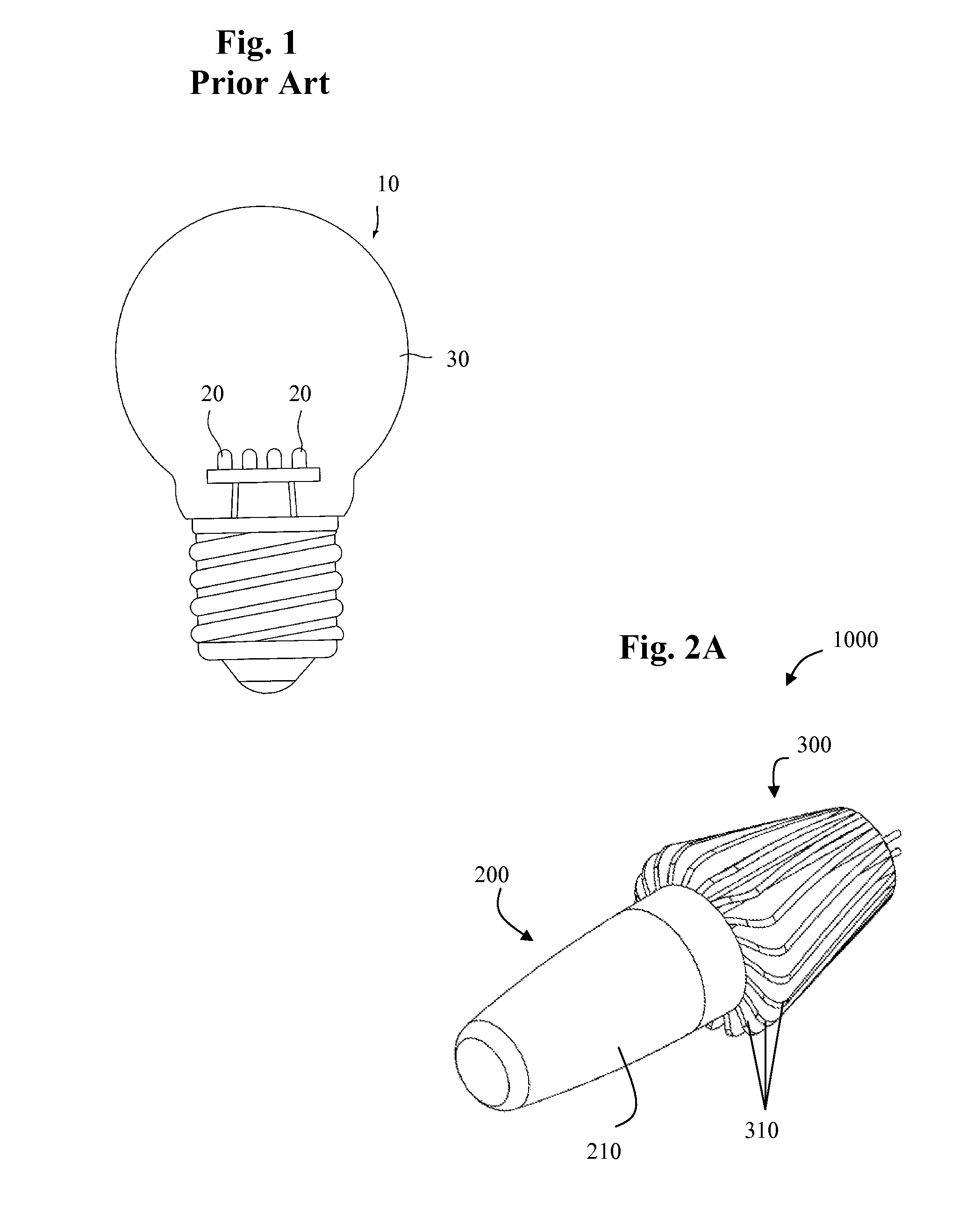
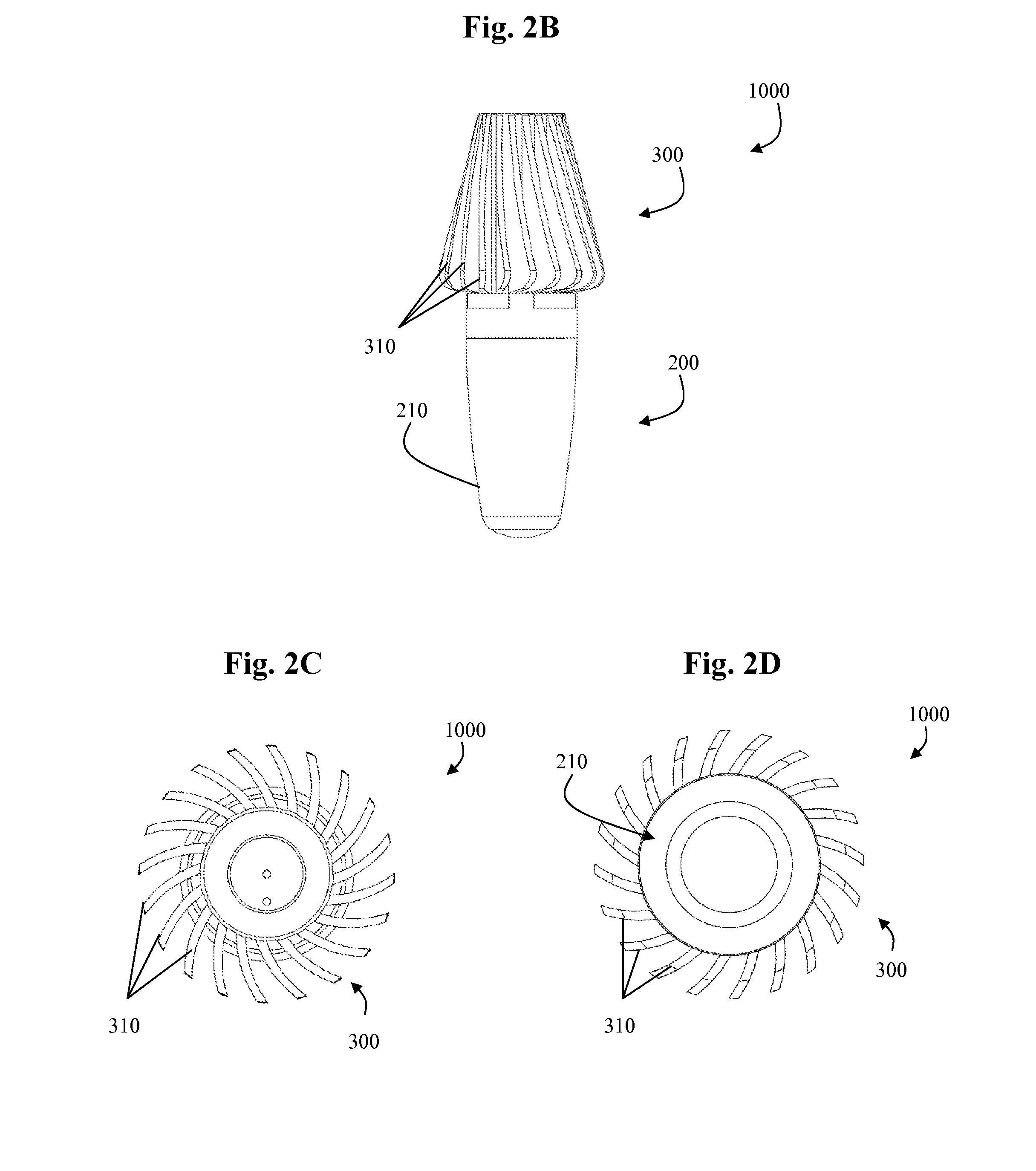
[0043]One embodiment of the present inventive illumination apparatus 1000 is illustrated in FIGS. 2A-2D. As shown in FIGS. 2A-2D, the illumination apparatus 1000 may generally comprise an optics module 200 that may be releasably secured to a heat dissipating element 300 via a releasable connection. As further depicted, the heat dissipating element 300 may comprise a plurality of radially projecting fins 310. The Figures also illustrate a lens cover 210 which may encapsulate and enclose other functional components of the optics module 200 there under.

[004...


PUM


Abstract

An illumination apparatus comprising an optics module wherein a driving circuit may be disposed within the proximal base portion of the optics module. The proximal base portion may further be releasably secured within an independent heat dissipating element. Such an apparatus may be very beneficial in light emitting diode (LED) applications due to its efficient conduction and dissipation of heat away from the LED semiconductor junction. Additionally, a releasable optics module comprising a plurality of LEDs and a driving circuit provides for cost efficient and environmentally friendly replacement of such a component at the end of its lifespan. The heat dissipating element (e.g. heat sink) may continue to be used, while only the optics module need be replaced or serviced as required. Precious environmental resources may thus be conserved and maintenance costs reduced while concurrently extending the lifespan of such an inventive illumination apparatus.

Description

CROSS REFERENCE TO RELATED APPLICATIONS[0001]Not applicable.STATEMENT REGARDING FEDERALLY SPONSORED RESEARCH OR DEVELOPMENT[0002]Not applicable.INCORPORATION-BY-REFERENCE OF MATERIAL SUBMITTED ON A COMPACT DISK[0003]Not applicable.BACKGROUND OF THE INVENTION[0004]1. Field of the Invention[0005]The present invention generally relates to conducting and dissipating heat from a light source, more particularly to effectively dissipating heat from a light source via a heat conducting element and an independent heat dissipating element further allowing for economical replacement of an optics module at the end of the lifespan of the light source disposed within the optics module.[0006]2. Background Art[0007]Over the past century, a variety of different types of light bulbs and other light sources have been developed. The most common type of light source is the incandescent light bulb, in which electric current is passed through a metal filament disposed in a vacuum, causing the filament to ...

Claims


Application Information

Patent Timeline
Patent Type & Authority Applications(United States)
IPC IPC(8): F21V21/00F21V29/02
CPCF21V29/78F21Y2101/02F21Y2115/10
Inventor MAXIK, FREDRIC S.WIDJAJA, ADDY S.SUN, WEIHENDERSON, DAVID
Owner LIGHTING SCI GROUP
Why Eureka
Try Eureka