Electric vehicle drive dc-dc converter and electric vehicle

Inactive Publication Date: 2010-02-11
MITSUBISHI HEAVY IND LTD
View PDF5 Cites 10 Cited by
  • Summary
  • Abstract
  • Description
  • Claims
  • Application Information

AI Technical Summary

Benefits of technology

[0013]In this manner, by driving the drive elements constituting the respective DC-DC converter units at different timings even when the smoothing capacitors are provided to the respective ones of the plurality of DC-DC converter units, the currents from the respective DC-DC converter units generated by the drive elements are equally divided to flow into the smoothing capacitors. Moreover, it is possible to decrease the amplitude of a ripple current produced in the smoothing capacitors by increasing the frequency of the ripple current. Therefore, since it is possible to decrease the capacity of the individual smoothing capacitors and the total capacity thereof, compared with the case of the DC-DC converter of Patent Document 1, and thus, it becomes advantageous in terms of cost. Since it is possible to achieve a small capacity of the smoothing capacitors, the rising and falling time during turning ON/OFF the current of the drive elements can be shortened by that much. Furthermore, similar to the above, since the plurality of DC-DC converter units are connected in parallel, it is possible to decrease not only the size of the smoothing capacitor but also the size of the choke coils or the power transistors as the drive sources, whereby the electric vehicle drive DC-DC converter and the electric vehicle become more cost effective.
[0014]Moreover, as described above, in an electric vehicle used for load handling, since the electric vehicle has a relatively large weight of e.g., 1 or 2 tons even with its small size because it needs to have a weight thereof corresponding to the weight of a load that it lifts, the DC-DC converter for driving a motor which is a drive source also requires a large output power. However, since the DC-DC converter has the above-described construction, the smoothing capacitor, the choke coil, the power transistor, and the like are allowed to be reduced in size thereof, and thus, low-cost and small-sized components can be used. Moreover, it is not necessary to prepare a large space for a power source. Furthermore, since a small-capacity capacitor is used, the current rising or falling time is shortened, and thus, the response characteristics of the electric vehicle can be improved.

Problems solved by technology

However, when electric power that can be handled is simply increased to comply with the required driving force, it is necessary to use large-capacity elements such as a step-up coil or a smoothing capacitor capable of

Method used


Image

  • Electric vehicle drive dc-dc converter and electric vehicle
  • Electric vehicle drive dc-dc converter and electric vehicle
  • Electric vehicle drive dc-dc converter and electric vehicle

Examples


first embodiment

[0026]First, an overview of an electric vehicle according to the present invention will be briefly described with reference to FIG. 6, which is a side view of a forklift truck as the electric vehicle using the electric vehicle drive DC-DC converter according to the present invention.

[0027]The forklift truck illustrated in FIG. 6 includes a pair of front wheels 41 and a pair of rear wheels 42 which are provided on the left and right sides in the lower part of a vehicle body 40, a mast 43 which is provided at the front part of the vehicle body 40, and a fork 44 which is frontwardly protruded from the mast 43. The front wheels 41 are driving wheels to which positive / negative rotational drive force is individually applied by independent drive motors (not illustrated) in response to a driver's manipulations on a steering wheel 45, a brake / accelerator pedal 46, and a forward / backward switching lever. The driving of the respective drive motors is controlled by a controller which is connect...

second embodiment

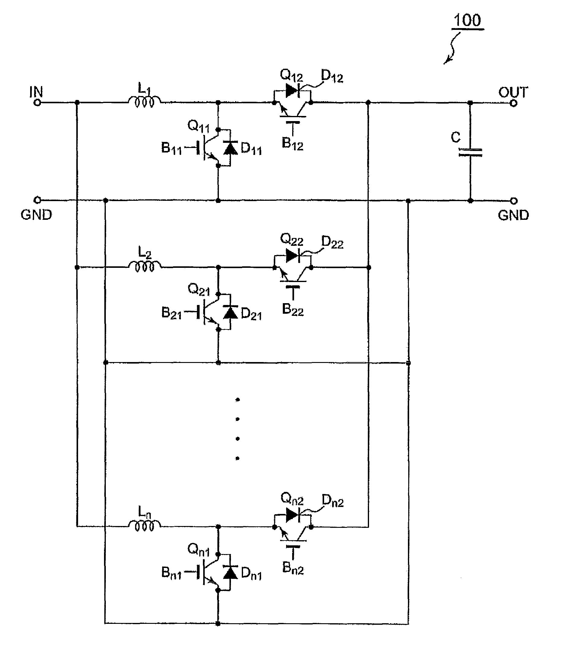
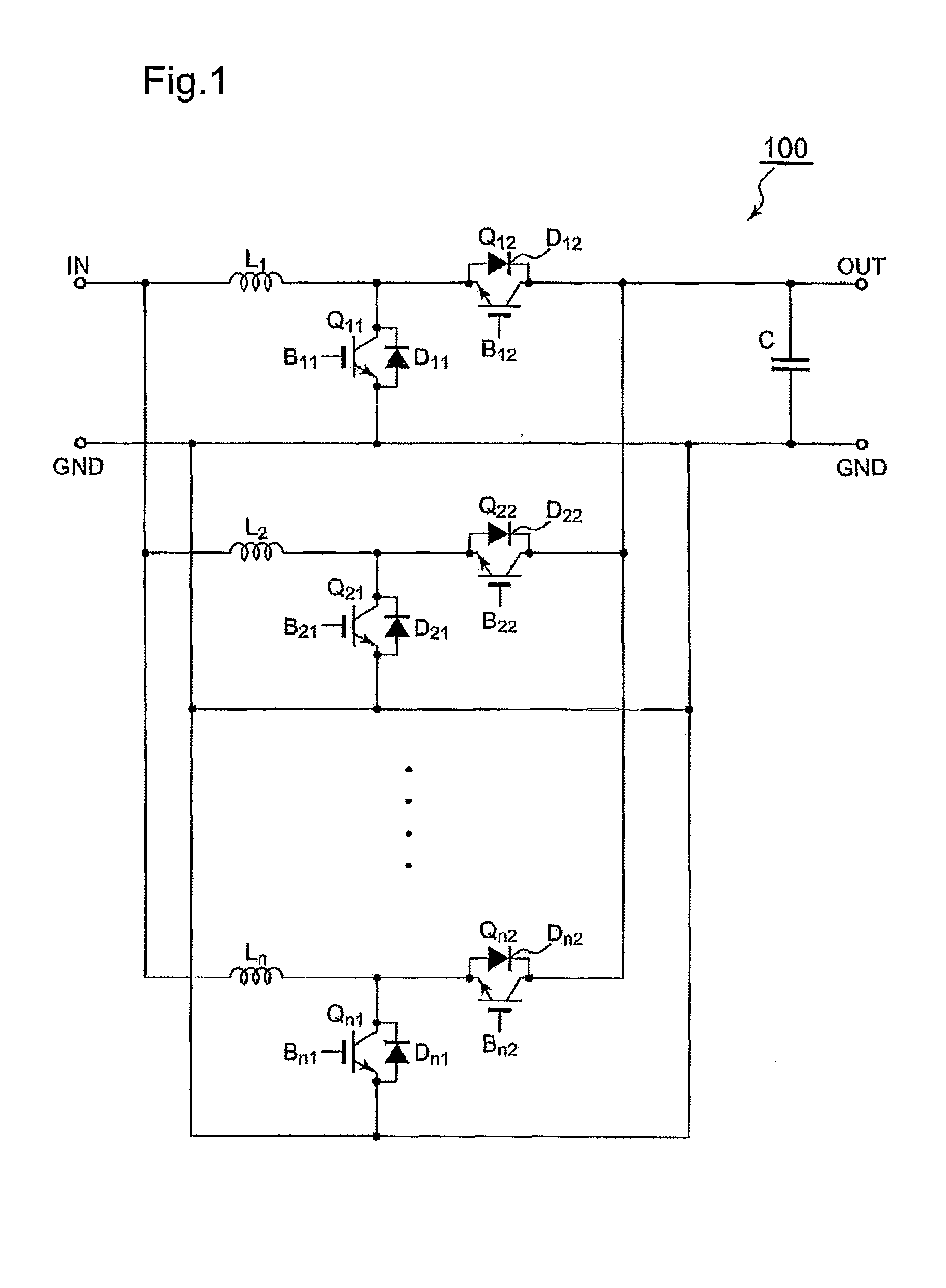
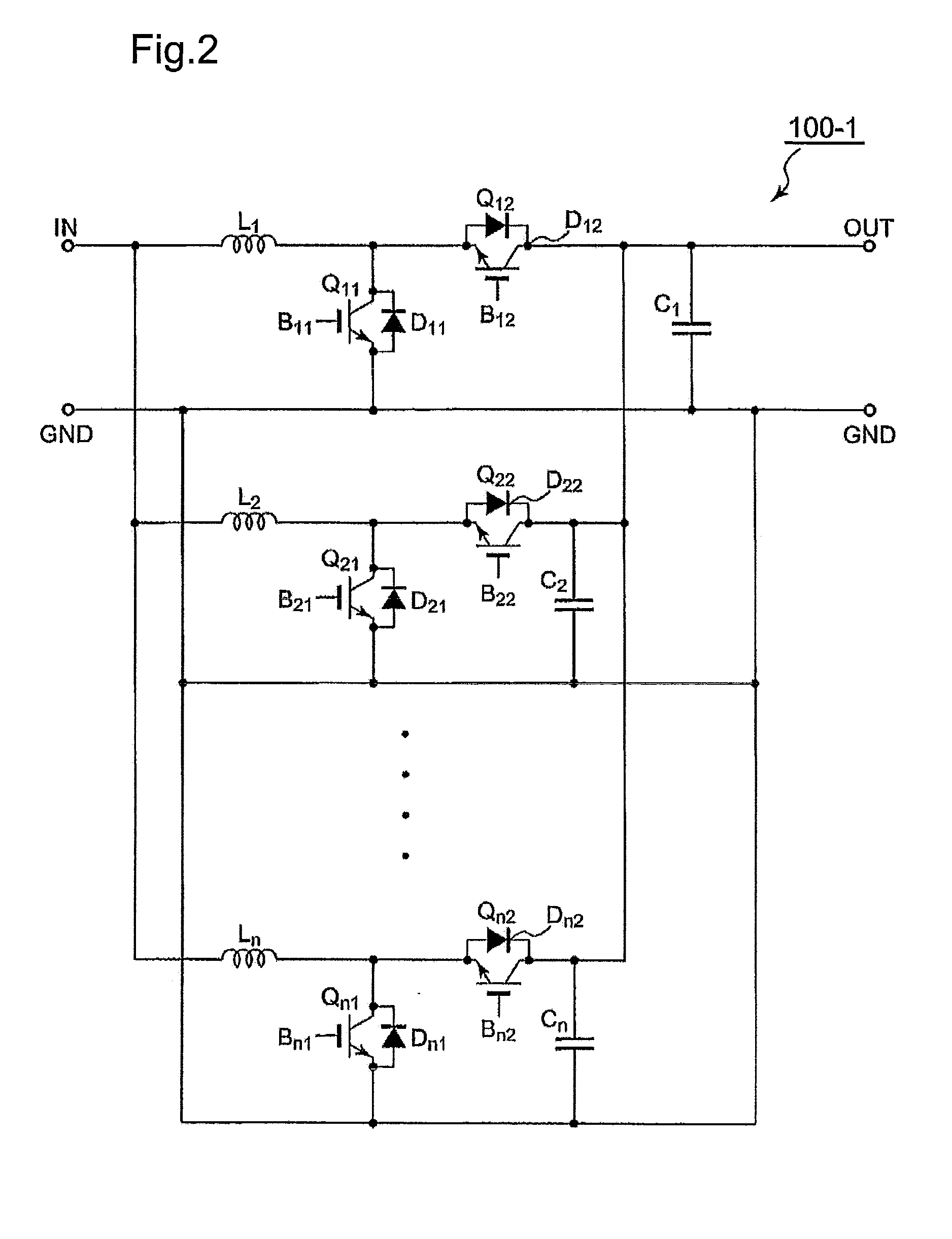
[0038]Next, a description of an electric vehicle drive DC-DC converter 100-1 according to a second embodiment of the present invention illustrated in FIG. 2 will be provided. In the above-described first embodiment of FIG. 1, one DC-DC converter unit is constructed by the choke coil L1, the step-up drive element Q11 having the FWD D11, and the step-down drive element Q12 having the FWD D12, and a plurality of similarly constructed DC-DC converter units is connected to the DC power source and the electric vehicle drive source (motor) as the load. Moreover, a single smoothing capacitor C is connected in parallel to the electric vehicle drive source (motor) as the load.

[0039]To the contrary, although the electric vehicle drive DC-DC converter 100-1 according to the second embodiment illustrated in FIG. 2 is similar to the first embodiment in that one DC-DC converter unit includes the coke coil L1, the step-up drive element Q11 having the FWD D11, and the step-down drive element Q12 hav...

third embodiment

[0046]Although in the first and second embodiments described above, the step-up drive elements Q11, Q21, . . . , and Qn1 are provided to correspond to the respective DC-DC converter units, by providing a plurality of groups of the step-up drive elements Q11, Q21, . . . , and Qn1 so as to correspond to the respective DC-DC converter units, it is possible to use the step-up drive elements Q11, Q21, . . . , and Qn1 which have a smaller rating such as withstand voltage or current capacity at this time.

[0047]Such a case is an electric vehicle drive DC-DC converter 100-2 according to a third embodiment of the present invention illustrated in FIG. 3. In the electric vehicle drive DC-DC converter 100-2 according to the third embodiment, a plurality of groups of step-up drive elements Q11, Q21, . . . , and Qn1, each group of which was provided so as to correspond to the respective DC-DC converter units in the first and second embodiment, is provided so as to correspond to the respective DC-D...


PUM


Abstract

An electric vehicle drive DC-DC converter and an electric vehicle are provided in which the electric vehicle drive DC-DC converter is constructed by connecting a plurality of DC-DC converter units in parallel, and in which a smoothing capacitor is allowed to be reduced in size thereof so that the DC-DC converter unit can be constructed in a small size, and electric power required by the electric vehicle can be coped with by only increasing the number of DC-DC converter units. Each of the DC-DC converter units includes: a coil having both ends thereof being connected to a DC power source and an electric vehicle drive source (motor); and a drive element which is connected in parallel to the electric vehicle drive source and driven in response to a signal supplied from a control circuit, the drive element having combined therewith a load current commutation diode. A single smoothing capacitor is connected in parallel to the electric vehicle drive source so that the respective drive elements of the plurality of DC-DC converter units are driven by the control circuit at different timings.

Description

TECHNICAL FIELD[0001]The present invention relates to an electric vehicle drive DC-DC converter, and more particularly, to a DC-DC converter having DC input and DC output for an electric vehicle, which is mainly used for load handling, such as a battery forklift or a hybrid battery forklift truck.BACKGROUND ART[0002]In an electric vehicle which is mainly used for load handling, such as a battery forklift or a hybrid battery forklift, a DC-DC converter having DC input and DC output is used for motor driving.[0003]In such an electric vehicle used for load handling, the electric vehicle has a relatively large weight of e.g., 1 or 2 tons even with its small size because it needs to have a weight thereof corresponding to the weight of a load that it lifts, and the electric vehicle requires a power corresponding to the weight of the electric vehicle per se.[0004]For this reason, a DC-DC converter for driving a motor which is a drive source also requires a large output power. However, when...

Claims


Application Information

Patent Timeline
IPC IPC(8): B60L1/00
CPCB60L7/12B60L11/1805B60L15/20B60L2200/42Y02T10/7275H02M3/1584H02M3/1588Y02T10/7005Y02T10/7216B60L2210/10B60L50/52Y02T10/64Y02T10/72Y02T10/70
Inventor OKAZAKI, YOSHIMIMORIMOTO, MASAYUKI
Owner MITSUBISHI HEAVY IND LTD
Why Eureka
Try Eureka