Operation of camshafts, particularly for an injection pump for diesel, having a running pulley driven in a lifting manner

a camshaft and pulley technology, which is applied in the direction of valve drives, machines/engines, gearing, etc., can solve the problems of high friction coefficient, achieve the effect of reducing material ratio mr, reducing roughness depth, and increasing roughness depth

Inactive Publication Date: 2010-02-18
ROBERT BOSCH GMBH
View PDF11 Cites 24 Cited by
  • Summary
  • Abstract
  • Description
  • Claims
  • Application Information

AI Technical Summary

Benefits of technology

[0009]Preferably, the material ratio MR of the return stroke section has a value of 5% to 30%, preferably from 10% to 25%, and particularly preferably, no more than 20%. The greater the average roughness depth RZ of a surface is, the lower the material ratio MR is. The material ratio MR, which is also referred to as the contact area percentage tP, is the ratio of the contact surface over a certain intersection line to the total area being considered, with regard to the reference span. Consequently a low material ratio MR results in a high friction so that with a low material ratio MR over the return stroke section, it is possible to reduce or avoid a slippage of the pressure roller.
[0010]By contrast, the average roughness depth RZ of the working stroke section has a value of 0.1 μm to 2.5 μm, preferably 0.5

Problems solved by technology

The resulting roughness depth RZ influences the coefficient of friction of the circumferen

Method used


Image

  • Operation of camshafts, particularly for an injection pump for diesel, having a running pulley driven in a lifting manner
  • Operation of camshafts, particularly for an injection pump for diesel, having a running pulley driven in a lifting manner
  • Operation of camshafts, particularly for an injection pump for diesel, having a running pulley driven in a lifting manner

Examples


Embodiment Construction

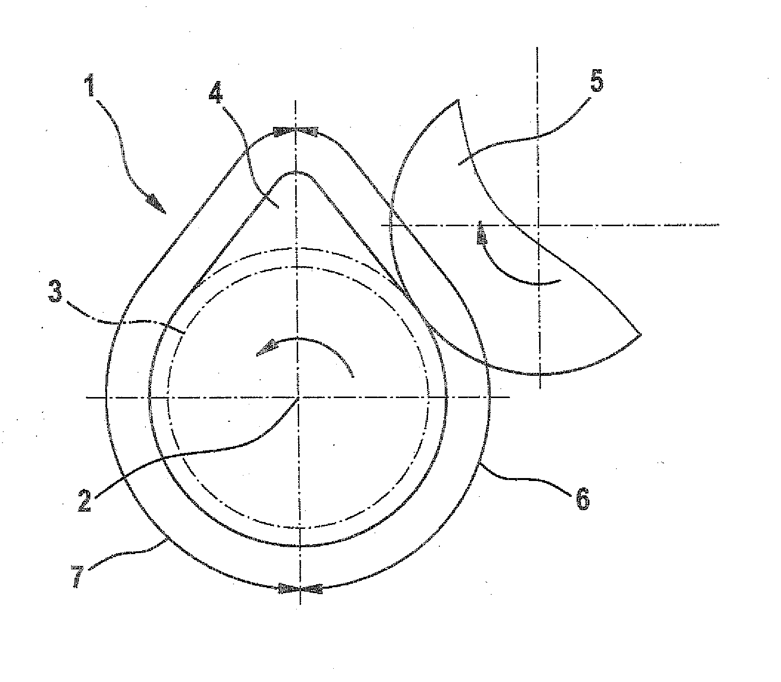
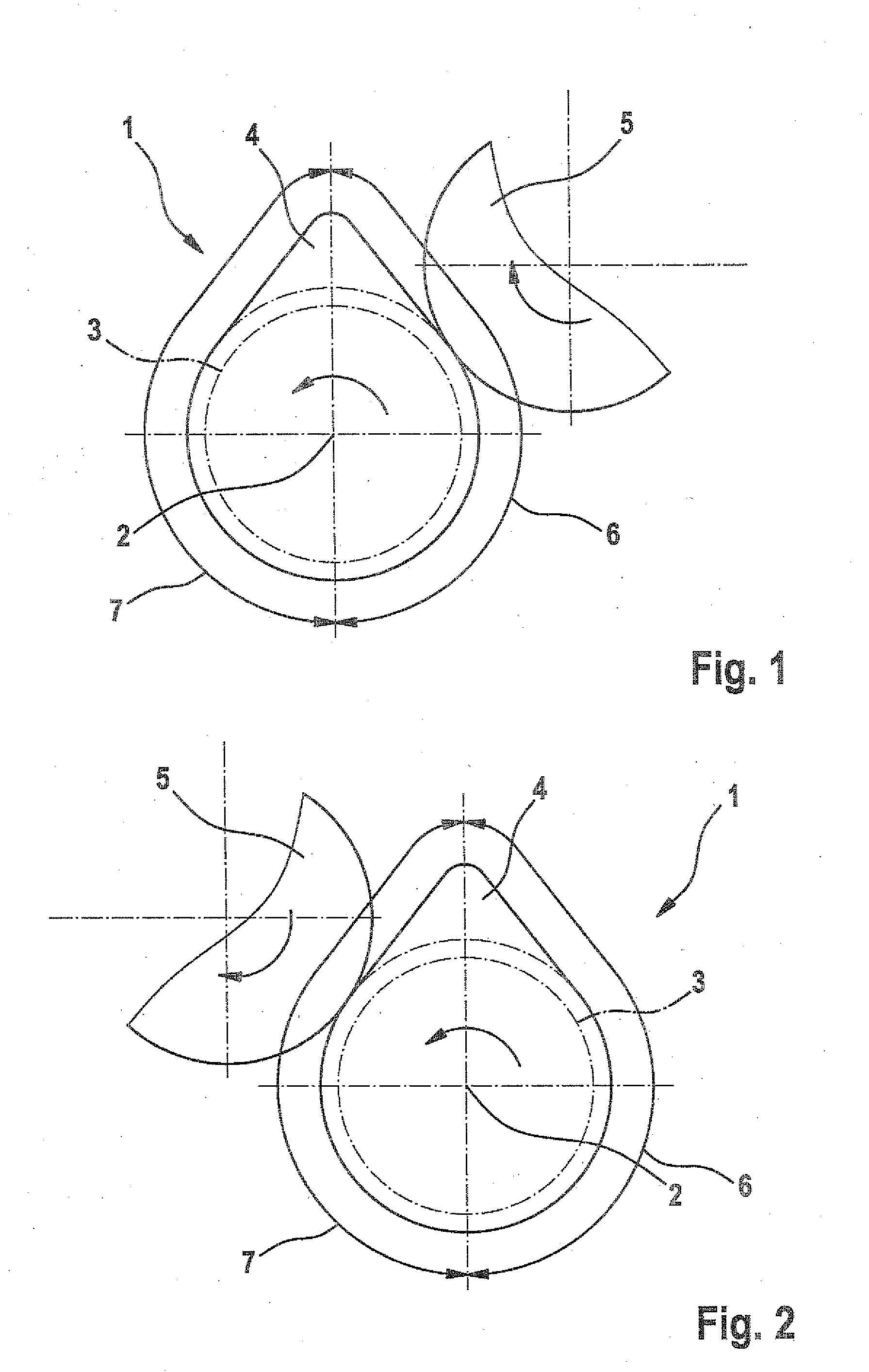
[0017]FIG. 1 is a view of a cam and a pressure roller, with a cross-sectional view of the camshaft, with the pressure roller in contact with the return stroke section;

[0018]FIG. 2 is a view of a cam and a pressure roller, with a cross-sectional view of the camshaft, with the pressure roller in contact with the working stroke section;

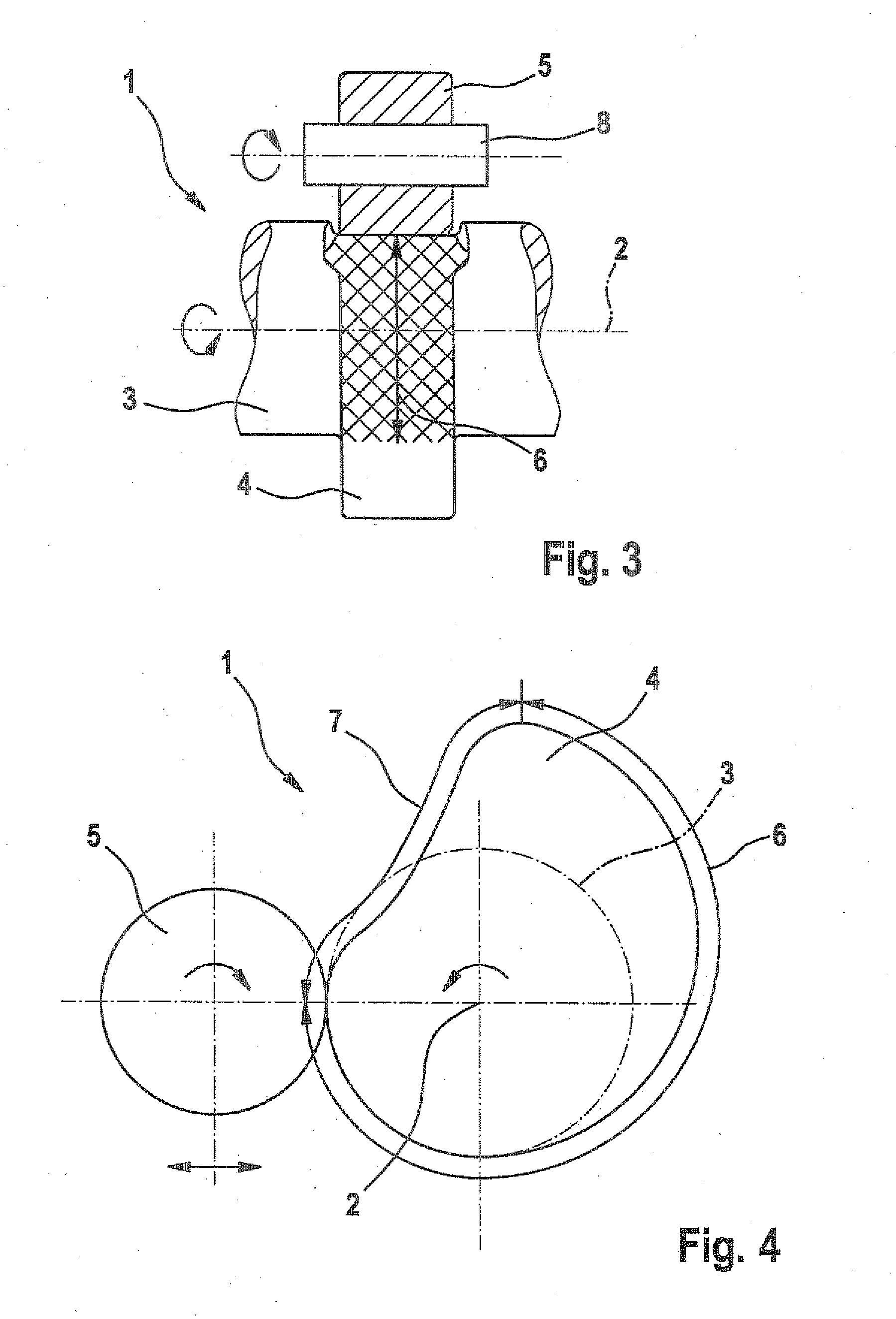
[0019]FIG. 3 is a side view of a camshaft with a cam incorporated into it, with the cam brought into contact with a pressure roller;

[0020]FIG. 4 is a schematic cross-sectional depiction of an alternative embodiment of a cam, which is brought into contact with a pressure roller; and

[0021]FIG. 5 is a schematic cross-sectional view of a camshaft with a double cam, which is embodied in the form of an ellipse.

[0022]In FIGS. 1 and 2, the camshaft drive is labeled with the reference numeral 1. It includes a camshaft 3 that rotates around a camshaft longitudinal axis 2. A cam labeled with the reference numeral 4 is integrated into the camshaft 3; the cam 4 likew...


PUM


Abstract

The invention provides for operation of camshafts, particularly for an injection pump for diesel. A camshaft rotates around a longitudinal axis of a camshaft. The camshaft has at least one cam being in cooperation with a pressure roller driven in a lifting manner. The pressure roller rotates on the peripheral surface of the cam. The upward stroke of the pressure roller is a working stroke during which the pressure roller moves away from the longitudinal axis of the camshaft. During a return stroke the pressure roller moves toward the longitudinal axis of the camshaft. The peripheral surface of the cam has a return stroke section and a working stroke section. The peripheral surface of the return stoke section has a greater friction value than the working stroke section. Thus an operation of camshafts for an injection pump for diesel is provided, securing a rotation of the pressure roller around the circumference of the cam within the whole speed range of the camshaft.

Description

[0001]The present invention relates to a camshaft drive, in particular for a diesel injection pump, which is used to produce a high pressure for diesel fuels in order to supply internal combustion engines.PRIOR ART[0002]Patent application DE 35 46 930 C2 has disclosed a camshaft drive, which includes a camshaft that is driven via the crankshaft of the internal combustion engine. The camshaft has a cam along whose circumference a pressure roller rolls. This produces a reciprocating motion in the pressure roller, that moves the pressure roller away from the camshaft longitudinal axis and, on the trailing side of the cam, moves the pressure roller back toward the camshaft longitudinal axis by means of the decreasing cam radius. This produces a continuous reciprocating motion of the pressure roller by means of the rotary motion of the camshaft; the pressure roller is accommodated in a sliding block in order to execute the linear reciprocating motion. The reciprocation thus produced can ...

Claims


Application Information

Patent Timeline
IPC IPC(8): F02M37/04
CPCF01L1/08F01L2101/00F16H53/02F02M59/102F16H25/14F01L2105/00F01L2301/00F01L2305/00F02M59/10F01L1/047F02M59/44
Inventor DUTT, ANDREASMEIER, GERHARD
Owner ROBERT BOSCH GMBH
Why Eureka
Try Eureka