Joining Method For Joining Components

a technology of joining components and components, applied in the direction of welding/cutting media/materials, manufacturing tools, welding apparatus, etc., can solve the problems of high apparative expenditure, high time need for joint production, and inability to meet the needs of weight optimization, etc., to achieve the effect of connecting materials

Inactive Publication Date: 2010-02-18
AIRBUS OPERATIONS GMBH
View PDF25 Cites 36 Cited by
  • Summary
  • Abstract
  • Description
  • Claims
  • Application Information

AI Technical Summary

Benefits of technology

[0012]One object of the present invention is to provide a method which allows connecting the materials ...

Problems solved by technology

However, it does not fulfil the needs for weight optimization which are common in the field of light weight construction to a very high extent.
Furthermore the usage of rivets leads to an additional weight in the joint areas.
Besides the apparative expenditure is high as well as the time need for the production of the joint.
Fusion welding methods evoke a significant shape distortion due to the comparatively high heat introduction which frequently has to be corrected during the following production steps.
Further joining of two titanium components is possible only with extremely high apparative expenditure which is merely in singular cases economically profitable.
Due to the generally high apparative expenditure which is needed for laser beam welding these methods are not suitable as a repair concept during the operation of the airplane.
This results in a high thermal load in the components.
Furthermore the apparative expenditure is high because the utilization of ovens is required.
This leads to the fact that the components to be joined have to be brought up to the high melting temperature of the solder which generally exceeds 450° C. This makes the method uns...

Method used


Image

  • Joining Method For Joining Components
  • Joining Method For Joining Components
  • Joining Method For Joining Components

Examples


second embodiment

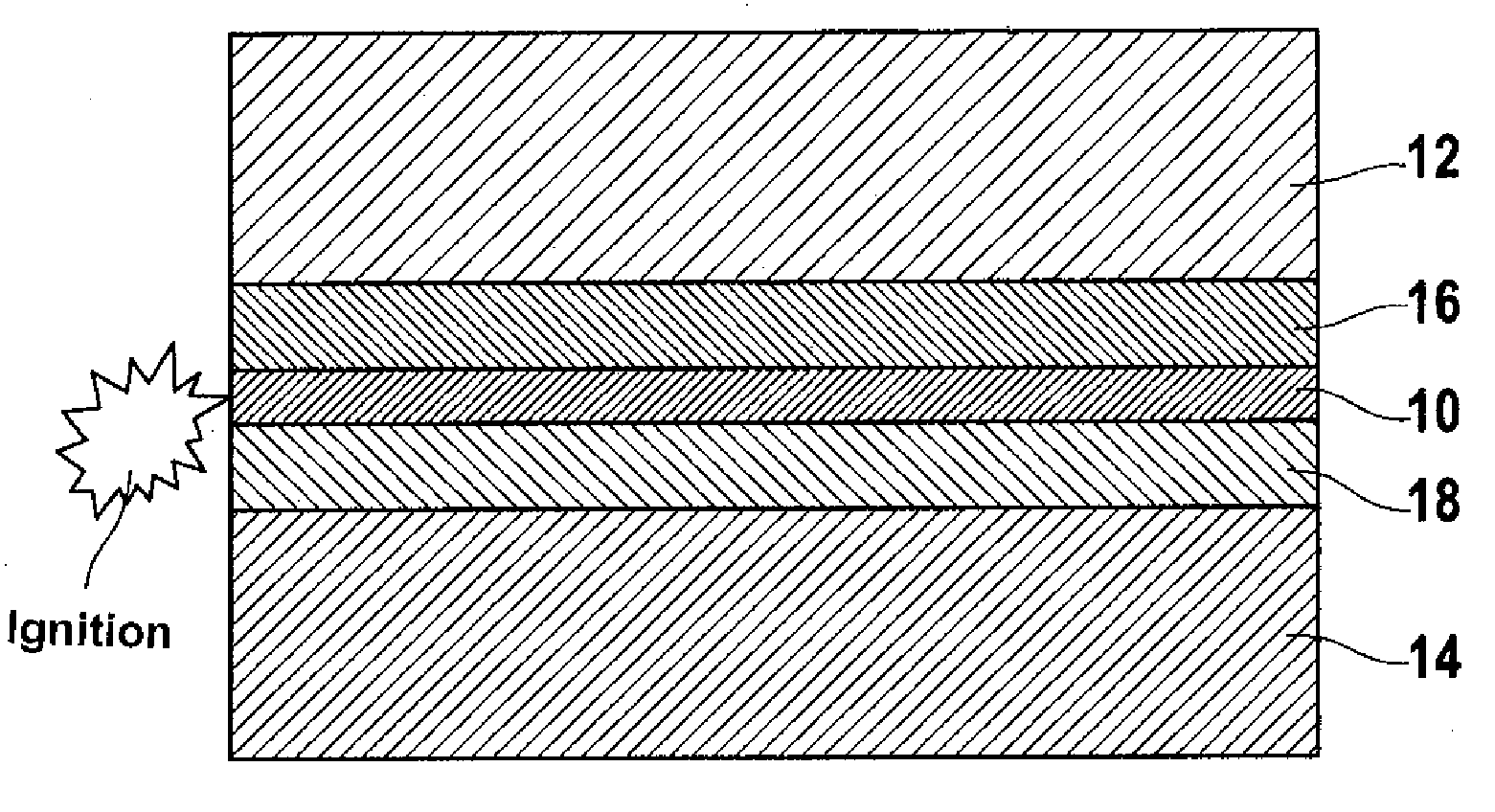
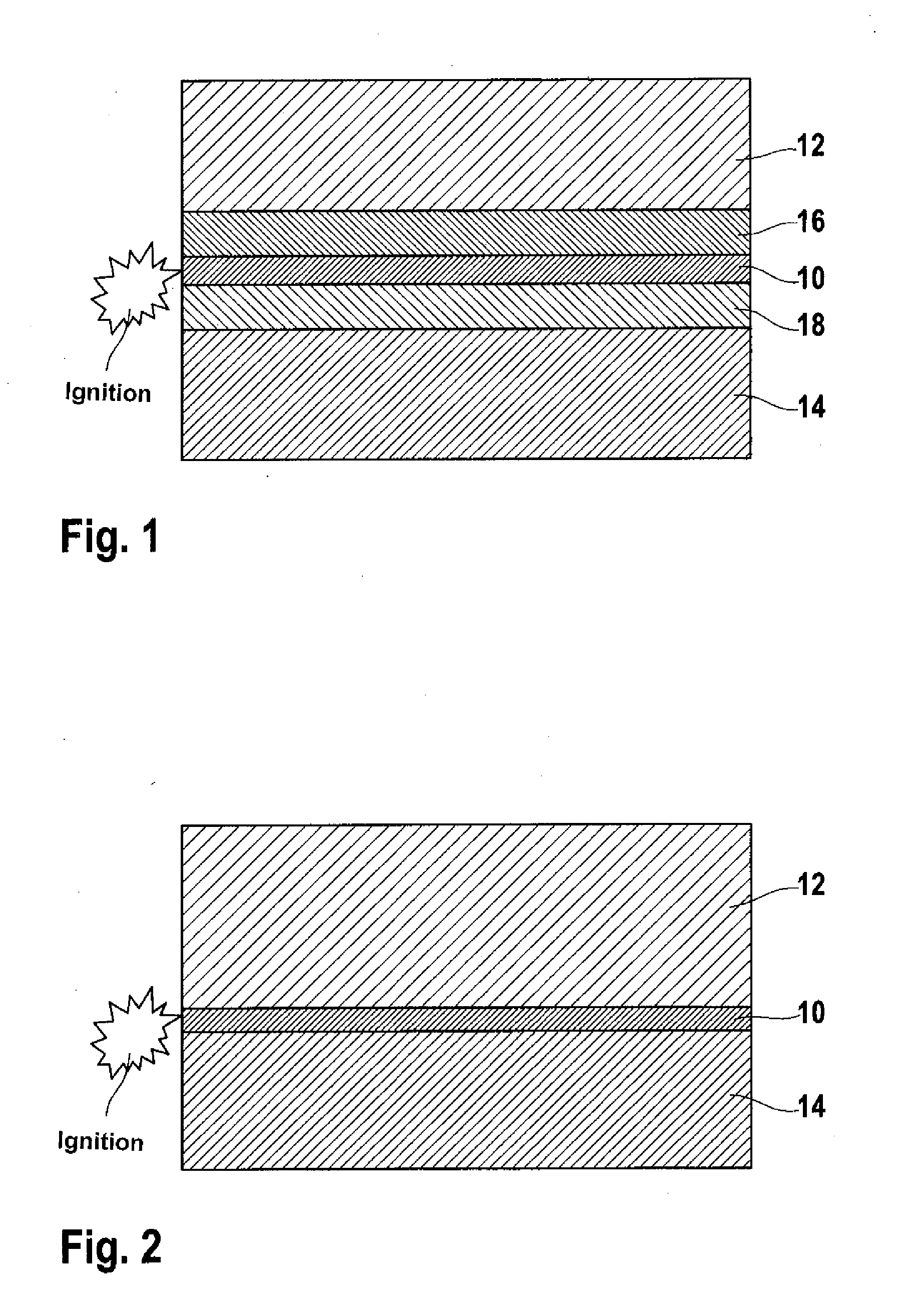
[0049]The nano- or microstructured materials 10 of the first and the method according to the present invention consist of reactants 20, 22 which react with each other in a self-propagating, exothermic chemical reaction if activation energy is introduced. For example the nano- or microstructured materials 10 can be metallic educts as for instance aluminium or titanium, which react to an intermetallic phase, in this case TiAl, Ti3Al or TiAl3, et cetera. These are only examples for a multitude of nano- or microstructured materials 10. Optionally also nickel, antimony and niobium as well as other metals can be used for instance.

[0050]The enumeration is here not restrictive. For an average person skilled in the art it is apparent that there is a multitude of further nano- or microstructured materials.

[0051]Thereby the self-propagating exothermic reaction does not have gaseous educts or products. Also a liquid phase is not possible on the product side though it is possible on the educt si...

first embodiment

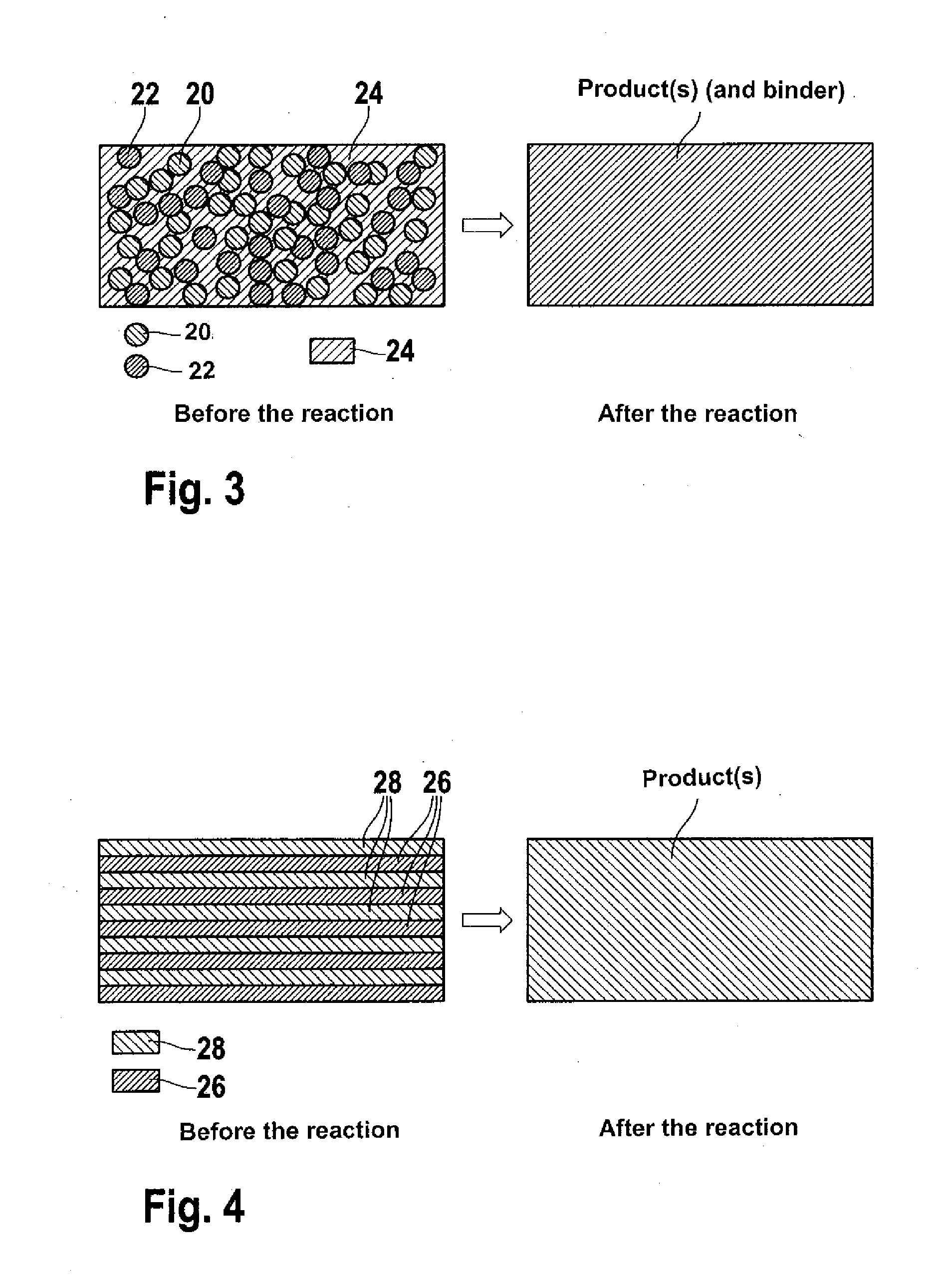
[0058]The particle size of the reactants 20, 22 lies in the nanometer or micrometer range and is connected by a binder 24 in this example, the joint material is for instance in form of a paste. The binder 24 can be solid as well as liquid and serves at first to make the paste manageable for the joining process. The reactants 20, 22 can be arranged within the binder 24 in any possible distribution which ensures the self-propagation of the chemical reaction. As shown in FIG. 3 two reactants 20, 22 or arbitrarily many reactants can be used, depending on the function and on the intended use. The binder 24 can but does not have to be involved in the self-propagating chemical reaction. The binder 24 can but does not have to be used as connecting material for the joint as described in the method according to the present invention.

[0059]FIG. 4 shows another possible arrangement of the reactants 20, 22 in the nano- or microstructured material. It is shown schematically the state before and a...


PUM

PropertyMeasurementUnit
Thicknessaaaaaaaaaa
Concentrationaaaaaaaaaa
Microstructureaaaaaaaaaa

Abstract

A method is provided for connecting components particularly in the field of aerospace wherein a first component is connected to a second component, comprising the following steps: arranging at least one nano- or microstructured material between the first and the second component, initiating an exothermic reaction of the nano- or microstructured material for connecting both components with each other.

Description

CROSS REFERENCE TO RELATED APPLICATION[0001]This application claims the benefit under 35 U.S.C. §119(e) of U.S. Provisional Application Ser. No. 60 / 914,821, filed on Apr. 30, 2007, which is incorporated by reference here in its entirety.FIELD OF THE INVENTION[0002]The present invention relates to a joining method for joining components by means of a self-propagating reaction in nano- or microstructured materials. The invention relates to a joining method which is inter alia suitable for connecting structure elements in the field of aircraft construction. The content of U.S. Provisional Application No. 60 / 914,821 is herein included by cross-reference.BACKGROUND OF THE INVENTION[0003]To this day the joining method of riveting is predominantly used in the field of aircraft construction. Riveting is very well characterized with respect to its mechanical properties of the connection and the long-run behaviour during the life cycle of an aircraft. However, it does not fulfil the needs for...

Claims


Application Information

Patent Timeline
IPC IPC(8): B23K31/02
CPCB23K1/0006
Inventor WILDEN, JOHANNESBERGMANN, JEAN PIERREJAHN, SIMONVUGRIN, TAMARAKNEPPER, PETER
Owner AIRBUS OPERATIONS GMBH
Why Eureka
Try Eureka